
Performance enhancement for motor field oriented control system

a technology of motor field and control system, applied in the direction of control system, dc motor speed/torque control, electrical apparatus, etc., can solve the problems of system providing substantial performance change, performance limitations at higher motor speeds, and interdependence of isub>q /sub>and isub>d /sub>control loops, etc., to achieve more robust and predictable control system, improve phase margin and stability, and limit the effect of “bandwidth”

Inactive Publication Date: 2006-03-02
HAMILTON SUNDSTRAND CORP
View PDF13 Cites 29 Cited by
  • Summary
  • Abstract
  • Description
  • Claims
  • Application Information

AI Technical Summary

Benefits of technology

[0027] In normal control theory, a control “zero” can be used to compensation closed loop poles in an attempt to improve phase margin and stability. However, compensation techniques are less preferable than the complete elimination of a pole (when possible) because it results in a much more robust and predictable control system.
[0028] It is also known that electronic power converters with actively regulated outputs (which includes motor drives) exhibit a constant power characteristic at the power converter's input power terminals. As the “constant power” terminology implies, when the input DC voltage to the inverter / converter is disturbed, the input current will respond in the opposite sense, i.e., increasing the input voltage will elicit an input current decrease and conversely a decrease in input voltage will elicit an input current increase. This “negative resistance” effect is well known and will tend to “un-damp” any resonant circuits or filters connected to the (input) power bus and could lead to instability in the entire power system. One important method is to limit the “bandwidth” of the constant power feature in the control algorithm to a sufficiently low level, generally well below the lowest corner frequency of any resonant circuits connected to the power bus. In this manner, any un-damping effects will fall outside any potential areas of resonance. Constant power bandwidth limiting can be provided in an FOC motor drive system by using the pole (integrator) provided in the PI (proportional-integrator) functional block. Thus, it is desired to have a single control loop “pole” for power system stability reasons, but no more than a single pole for control stability reasons as discussed above.

Problems solved by technology

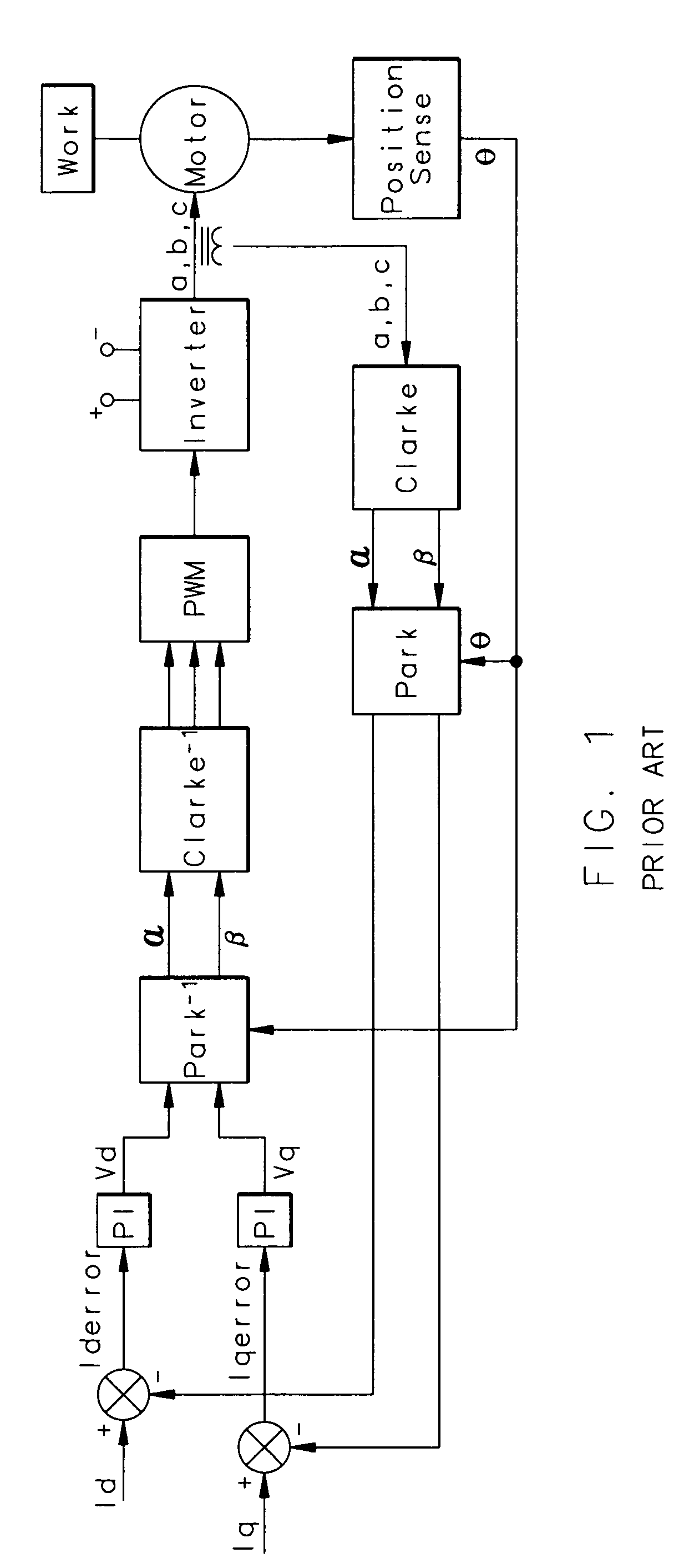
The basic control described above assumes the two loops are independent, however, the Iq and Id control loops are not actually completely independent from one another.
The inter-dependence of the Iq and Id control loops raises a problem.
While this is true for the above-described low motor speed operating condition, this basic FOC system provides substantial performance change and performance limitations at higher motor speeds.
Unwanted errors (disturbances) were created in the d-axis control loop.
It is generally undesirable to have two cascaded integrators in a closed loop control system, because together they will (by definition) create opportunity for 180 degree total phase shift and perhaps lead to control instability.
Because the conventional FOC system necessarily incorporates PI (proportional-integrator) functions in both q-axis and d-axis control loops, and because the motor impedance forces the system into a 2-pole closed loop system response as described above, the standard FOC system is potentially prone to control stability problems.
However, compensation techniques are less preferable than the complete elimination of a pole (when possible) because it results in a much more robust and predictable control system.
This “negative resistance” effect is well known and will tend to “un-damp” any resonant circuits or filters connected to the (input) power bus and could lead to instability in the entire power system.

Method used


Image

  • Performance enhancement for motor field oriented control system
  • Performance enhancement for motor field oriented control system
  • Performance enhancement for motor field oriented control system

Examples


Embodiment Construction

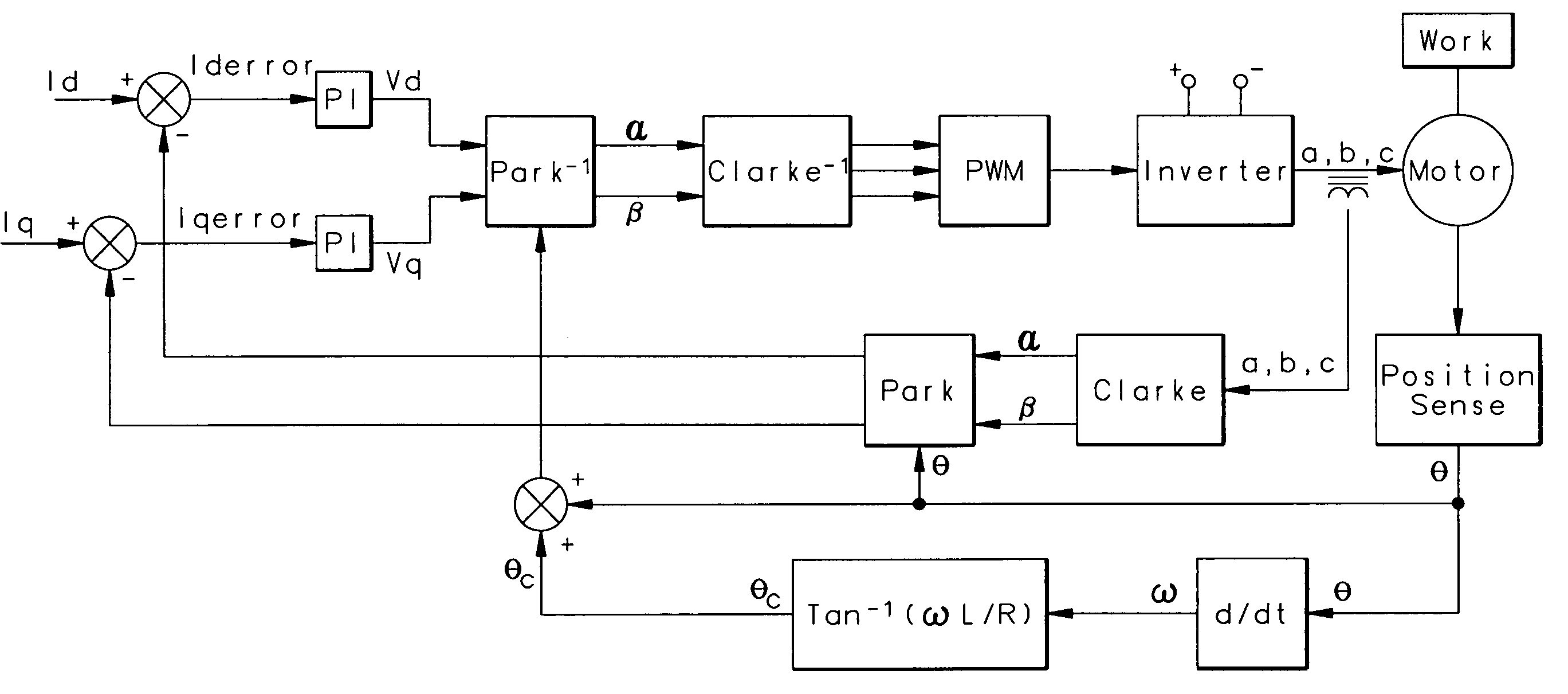
[0037]FIG. 3 illustrates a disclosed control. The basic configuration of the conventional FOC algorithm is retained. However, an ARCTAN function (Tan−1) is added that provides a phase shifting angle in response to motor rotational speed (electrical frequency). Specifically, the ARCTAN function provides an angle precisely equal to the motor winding impedance angle. As can be appreciated from FIG. 3, the ARCTAN function receives the time derivative of the sensed angular position of the motor to determine the frequency, ω. This angle θc, output from the ARCTAN function, is used to rotate the inverse Park function (Park−1) alone (that is not the forward Park function) with a polarity such that as the motor impedance angle changes from zero to +90 degrees, the input angle θc to the Park−1 block will also change from 0 to +90 degrees. In this manner, the undesired effect of the motor impedance change over the operating speed range will be precisely eliminated. The end result is that for t...


PUM


Abstract

A motor controller of the sort having both a transformation function for transforming three-phase feedback information into two components, and then changing an error signal for each of the two components back into three-phase correction numbers is provided with an ARCTAN correction function. The ARCTAN correction function takes in the time derivative of the changing angular position of the motor rotor, and creates a correction factor that is supplied back to the transformation function for changing the two error signals back into three. By supplying this correction ARCTAN function, the control eliminates a disturbance that may have occurred in the prior art at higher frequencies wherein both of the control loops for the two components needed to come into play to correct an error on either of the two loops.

Description

BACKGROUND OF THE INVENTION [0001] This invention relates to a motor controller wherein a frequency of the motor's operation is utilized to provide a correction function for eliminating a disturbance on a two-loop control path, with the elimination of the disturbance allowing the control path to provide a single loop correction on either path. [0002] Motor controllers are used in conjunction with motors to provide variable and controllable speed for various applications. While this invention is particularly directed for aircraft application, it is not so limited. [0003] In aircraft applications, motor controllers are used for both low power and high power applications. Main engine starting is accomplished with a motor controller in conjunction with the main electrical power generator (acting as a motor). This is a high power application. The same is true for a motor driven hydraulic pump aircraft application. It is common practice to use the main engine starting motor controller to ...

Claims


Application Information

Patent Timeline
Patent Type & Authority Applications(United States)
IPC IPC(8): H02P7/36H02P27/00
CPCH02P21/0035H02P2207/05H02P21/06H02P21/22
Inventor BAKER, DONAL E.PLUDE, CURTIS J.MILES, GARY L.PFEIFFER, MARK W.
Owner HAMILTON SUNDSTRAND CORP
Learn More