

High-frequency receiver and portable device using the same
a technology of high-frequency receivers and portable devices, applied in the field of high-frequency receivers, can solve the problems of difficult to achieve the requirement of battery-operated portable devices, and achieve the effect of reducing image interference and less power
- Summary
- Abstract
- Description
- Claims
- Application Information
AI Technical Summary
Benefits of technology
Problems solved by technology
Method used
Image

Examples
exemplary embodiment 1
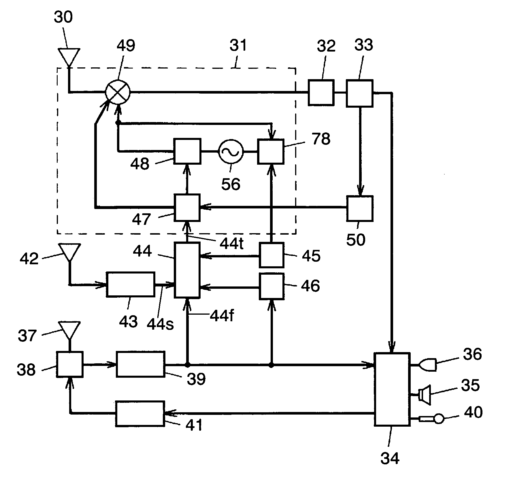
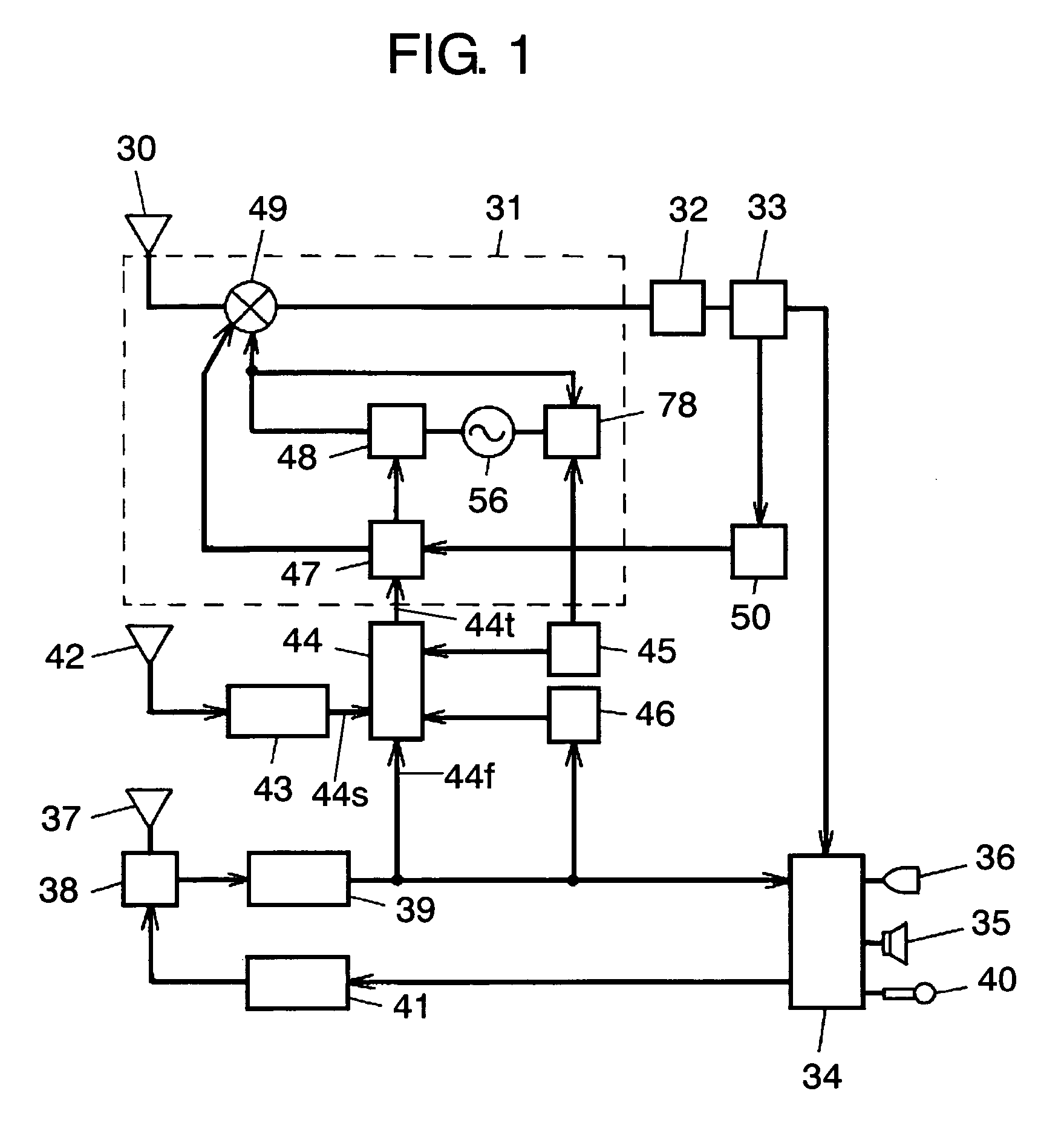
[0037] The first exemplary embodiment of the present invention is demonstrated hereinafter with reference to accompanying drawings. FIG. 1 shows a block diagram illustrating a portable high-frequency receiver. Antenna 30 for receiving television (TV) broadcastings receives, e.g. VHF broadcasting band as a first frequency band and UHF broadcasting band as a second frequency band. The frequencies of those bands range from approx. 55.25 MHz to 801.25 MHz. Antenna 30 connects to high-frequency receiver 31 at its output terminal. Receiver 31 selects signals of a desirable channel from among the received high-frequency signals, and outputs signals converted into an intermediate frequency of 45.75 MHz.
[0038] Demodulator 32 demodulates the intermediate frequency signals supplied from receiver 31. Decoder 33 receives output signals from demodulator 32 carries out vitebi-correction and reed-solomon correction, and the signals having undergone those corrections are output to speaker 35 or liq...
exemplary embodiment 2
[0107] A mixer in accordance with the second embodiment is described hereinafter with reference to FIG. 7. FIG. 7A shows a block diagram of the mixer. In this second embodiment, vector synthesizers 202, 203, limiting circuits 206, 207, and switches 208, 209 are additionally provided to the construction of the first embodiment. Switches 208, 209 are used as one of mixer input switching means. Elements similar to those used in the first embodiment have the same reference marks.
[0108] In FIG. 7A, switch 67 connects to each one of four outputs from frequency divider 201. Switch 67 is connected to vector synthesizers 202, 203 at its common terminal 67k. When switch 67 selects contacts 67b, the output signals from divider 201 connect to vector synthesizer 202, so that four output signals are fed into synthesizer 202. Limiting circuits 206, 207 connect to synthesizers 202, 203 respectively, and they limit the signals supplied from synthesizers 202, 203 to a given level before the signals ...
exemplary embodiment 3
[0119] The third exemplary embodiment is described hereinafter with reference to FIG. 8, which shows a block diagram of a high-frequency receiver in accordance with the third embodiment. Elements similar to those used in FIG. 2 described in the first embodiment have the same reference marks here.
[0120] Oscillator 356 placed approx. at the center of FIG. 8 oscillates signals having frequencies ranging from 700 MHz to 1700 MHz. In other words, oscillator 356 is a local oscillator having frequencies twice as much as that of the first embodiment. Those oscillating frequencies are determined by inductor 368 and variable capacitance diode 369, and the capacitance of respective capacitors 372, 373, 375, and 376 are adjusted at given values. For the respective receivable bands, changing characteristics of single-tuned filters 52, 62, double-tuned filter 54, 64 and local oscillator 356 with respect to tuning voltages are approximated to each other so that the difference between the frequenc...
PUM
 Abstract
Description
Claims
Application Information