Control apparatus for an automatic transmission and related control method

a control apparatus and automatic transmission technology, applied in the direction of electric control, machines/engines, transportation and packaging, etc., can solve the problems of increasing the engine brake force, and reducing the control effect of the automatic transmission. , to achieve the effect of suppressing undesirable acceleration or shock, increasing control, and simple logical arrangemen

Inactive Publication Date: 2006-03-02
DENSO CORP
View PDF3 Cites 42 Cited by
  • Summary
  • Abstract
  • Description
  • Claims
  • Application Information

AI Technical Summary

Benefits of technology

[0008] In view of the foregoing problems of the prior art techniques, the present invention has an object to provide a control apparatus for an automatic transmission that is capable of accurately setting start timing of an engine output increasing control when a downshift operation is executed based on a driver's intent to decelerate, and also capable of suppressing undesirable acceleration or shock occurring when the engine output increasing control is performed, and further capable of executing the engine output increasing control with a simple logical arrangement and a relatively smaller number of parameter settings.

Problems solved by technology

According to these automatic transmissions, when a vehicle is traveling on a descending road, a sufficient engine brake force may not be obtained even when an accelerator is operated to an OFF state.
A required engine brake will not be obtained at a desired timing.
This will temporarily increase the engine brake force and cause a shift shock.
Furthermore, abruptly increasing a transmission torque of a frictional engaging element to shorten a shift time, for example by controlling a hydraulic pressure of the automatic transmission, will quickly increase the engine rotational speed and accordingly the braking torque will abruptly increase and a large shift shock will occur.
Furthermore, there is a delay time before the frictional engaging element of an automatic transmission is actually disengaged or engaged.
Furthermore, there is a delay time before the engine output actually starts increasing when a throttle opening control is performed to increase the engine output.
However, the delay time required for the frictional engaging element to actually disengage or engage during a downshift operation is dependent on not only the oil temperature in a hydraulic pressure control circuit or the engine rotational speed but also a vehicle speed or a torque acting on this frictional engaging element when the downshift control is executed.
Furthermore, the delay time will be dependent on the operating conditions including a slip control of a lockup clutch.
Therefore, relying only a timer to set the control start time is not always accurate even if the effects of the oil temperature or the engine rotational speed are taken into consideration and, accordingly, a throttle valve opening control (i.e. engine output increasing control) may not be started at appropriate timing.
Hence, the throttle valve opening control possibly starts at inappropriate timing and a driver will feel badly or receive a shock caused by the throttle valve opening control during a downshift operation.
Furthermore, appropriately setting reference values of a timer considering the effects of the oil temperature or the engine rotational speed requires repetitive experiments for determining these values.
Not only the control logic becomes complicated but also the many parameter settings will be required.

Method used


Image

  • Control apparatus for an automatic transmission and related control method
  • Control apparatus for an automatic transmission and related control method
  • Control apparatus for an automatic transmission and related control method

Examples


first embodiment

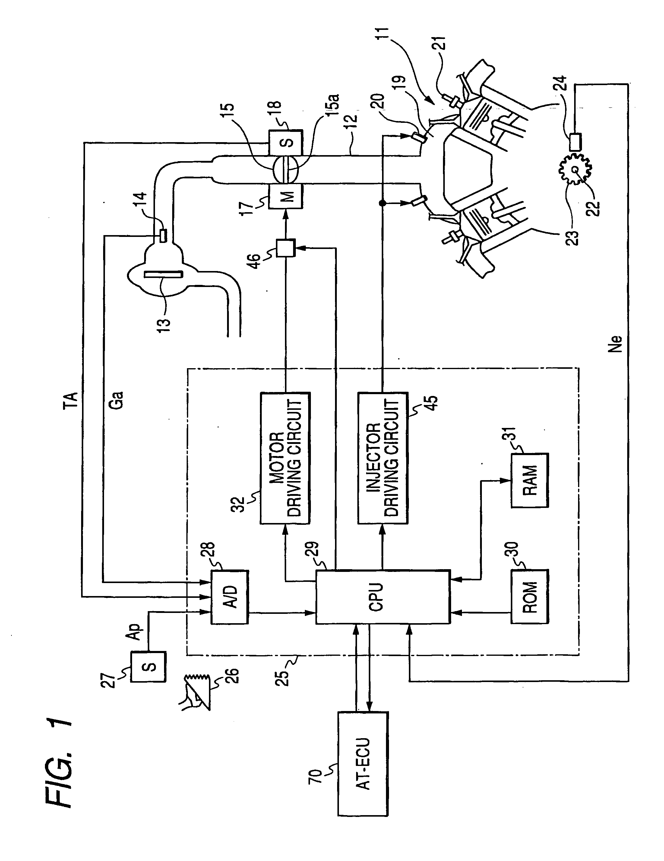
[0061] A first embodiment of the present invention will be explained with reference to FIGS. 1 to 22. FIG. 1 schematically shows an overall arrangement of a control system for an internal combustion engine 11. The engine 11 has an intake pipe 12, an air cleaner 13 disposed at an upstream portion of the intake pipe 12, and an air flow meter 14 disposed at a downstream side of the air cleaner 13 to measure an intake air amount Ga. Furthermore, a throttle valve 15 is provided at a downstream side of the air flow meter 14. A motor 17, such as a DC motor, is connected to a rotational shaft 15a of the throttle valve 15. The motor 17 generates a driving force for controlling an opening degree of the throttle valve 15 (i.e. throttle opening degree). A throttle opening degree sensor 18 detects the throttle opening degree.

[0062] The intake air, after having passed the throttle valve 15, flows into an intake manifold 19 that introduces the intake air into each cylinder of the engine 11. A pre...

second embodiment

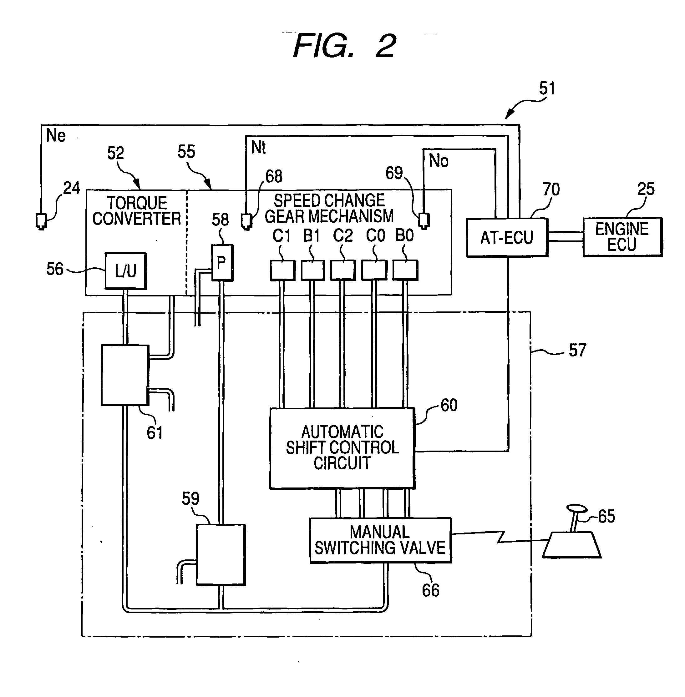
[0152]FIGS. 23 and 24 show a second embodiment of the present invention that is made based on the fact a gear ratio (=input shaft rotational speed Nt / output shaft rotational speed No) decreases when the input shaft rotational speed Nt decreases after the ETC cooperative downshift control starts. At the timing the gear ratio falls below a set value after the ETC cooperative downshift control is started, it is presumed that the hydraulic pressure of the to-be-disengaged clutch is already reduced to a hydraulic pressure level equivalent to a predetermined transmission torque capacity that causes no undesirable acceleration or shock even if the engine output increasing control is started. And, under such assumption, the engine output increasing control is started at this timing.

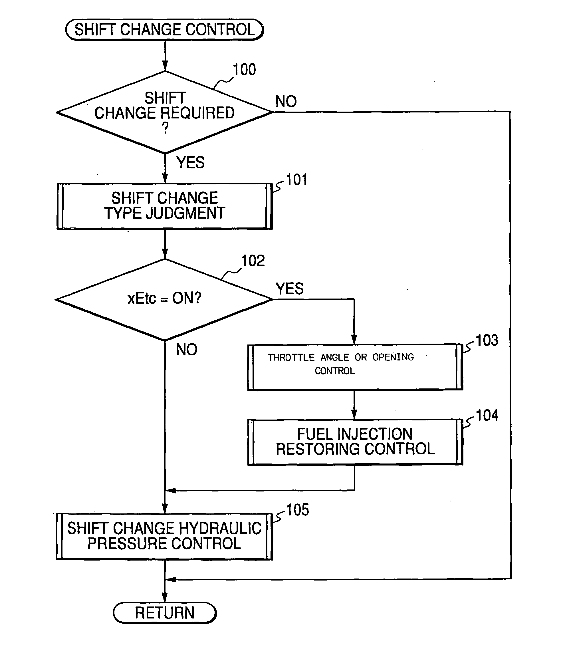
[0153]FIG. 24 shows a throttle opening control start judging routine according to the second embodiment of the present invention. When this routine starts, a judgment is made in step 223 as to judge whether or n...

third embodiment

[0155] In some cases, as shown in FIG. 25, the input shaft rotational speed Nt or the gear ratio may not decrease sufficiently depending on engine control conditions even after the ETC cooperative downshift control is started; In such a case, according to the above-described first and second embodiments, the engine output increasing control will not start for a relatively long time.

[0156] Hence, according to a third embodiment of the present invention shown in FIGS. 25 and 26, an elapsed time timer (i.e. timer means) is provided to measure the time having elapsed after the ETC cooperative downshift control is started. When the engine output increasing control does not start even after the elapsed time exceeds the set value, the engine output increasing control is forcibly started.

[0157]FIG. 26 shows a throttle opening control start judging routine according to the third embodiment of the present invention. When this routine starts, a judgment is made in step 223 as to whether or n...


PUM


Abstract

In executing an ETC cooperative downshift operation based on a driver's intent to decelerate, this system executes an engine output increasing control (e.g. a combination of a throttle opening control and a fuel injection restoring control) for increasing the engine output irrespective of driver's accelerator operation. At the timing a reduction amount in an input shaft rotational speed Nt exceeds a predetermined value K after the ETC cooperative downshift control is started, it is presumed that the hydraulic pressure of a to-be-disengaged clutch is already reduced to a hydraulic pressure level equivalent to a predetermined transmission torque capacity that causes no undesirable acceleration or shock even if the engine output increasing control is started. And, under such assumption, the engine output increasing control is started at this timing. Accordingly, the present invention can accurately set the start timing of the engine output increasing control so as to suppress any undesirable acceleration or shock caused by the engine output increasing control.

Description

CROSS-REFERENCE TO RELATED APPLICATION [0001] This application is based upon and claims the benefit of priority from earlier Japanese Patent Application No. 2004-252220 filed on Aug. 31, 2004 so that the description of which is incorporated herein by reference. BACKGROUND OF THE INVENTION [0002] The present invention relates to a control apparatus for an automatic transmission that can improve a downshift control to be executed in response to a driver's intent to decelerate, and also relates to a related control method. [0003] The automatic transmissions for automotive vehicles include a hydraulic pressure control circuit to select engagement / disengagement of a plurality of frictional engaging elements, such as hydraulically controlled clutches and brakes, to realize a plurality of gear stages. According to these automatic transmissions, when a vehicle is traveling on a descending road, a sufficient engine brake force may not be obtained even when an accelerator is operated to an OF...

Claims


Application Information

Patent Timeline
Patent Type & Authority Applications(United States)
IPC IPC(8): B60K41/04B60W10/00B60W10/04B60W10/06B60W10/10B60W10/11B60W10/115F02D29/00F02D41/12F02D45/00F16H59/08F16H59/18F16H59/42F16H61/04F16H61/21F16H61/68F16H61/684F16H61/686F16H63/50
CPCB60W10/06Y10T477/675B60W30/19B60W2510/1015B60W2710/0616F02D29/02F02D41/023F02D2250/21F16H61/061F16H61/21F16H61/686F16H63/502F16H2306/42F16H2306/54F02D41/123F02D41/0002F16H2061/0496Y02T10/42Y10T477/6937B60W10/115Y02T10/40
Inventor NAKAJIMA, NOBUYORIMURAKAWA, TAKAJIKOZAKI, TETSUJI
Owner DENSO CORP
Why Eureka
Try Eureka