
Storage device control apparatus

a control apparatus and storage device technology, applied in the field of storage device control apparatus, can solve the problems of data not being transmitted, data being limited to transmitting data at high speeds in a parallel interface, and difficult to mount circuit components, so as to and increase the reliability of the memory system

Inactive Publication Date: 2006-03-02
HITACHI LTD
View PDF6 Cites 79 Cited by
  • Summary
  • Abstract
  • Description
  • Claims
  • Application Information

AI Technical Summary

Benefits of technology

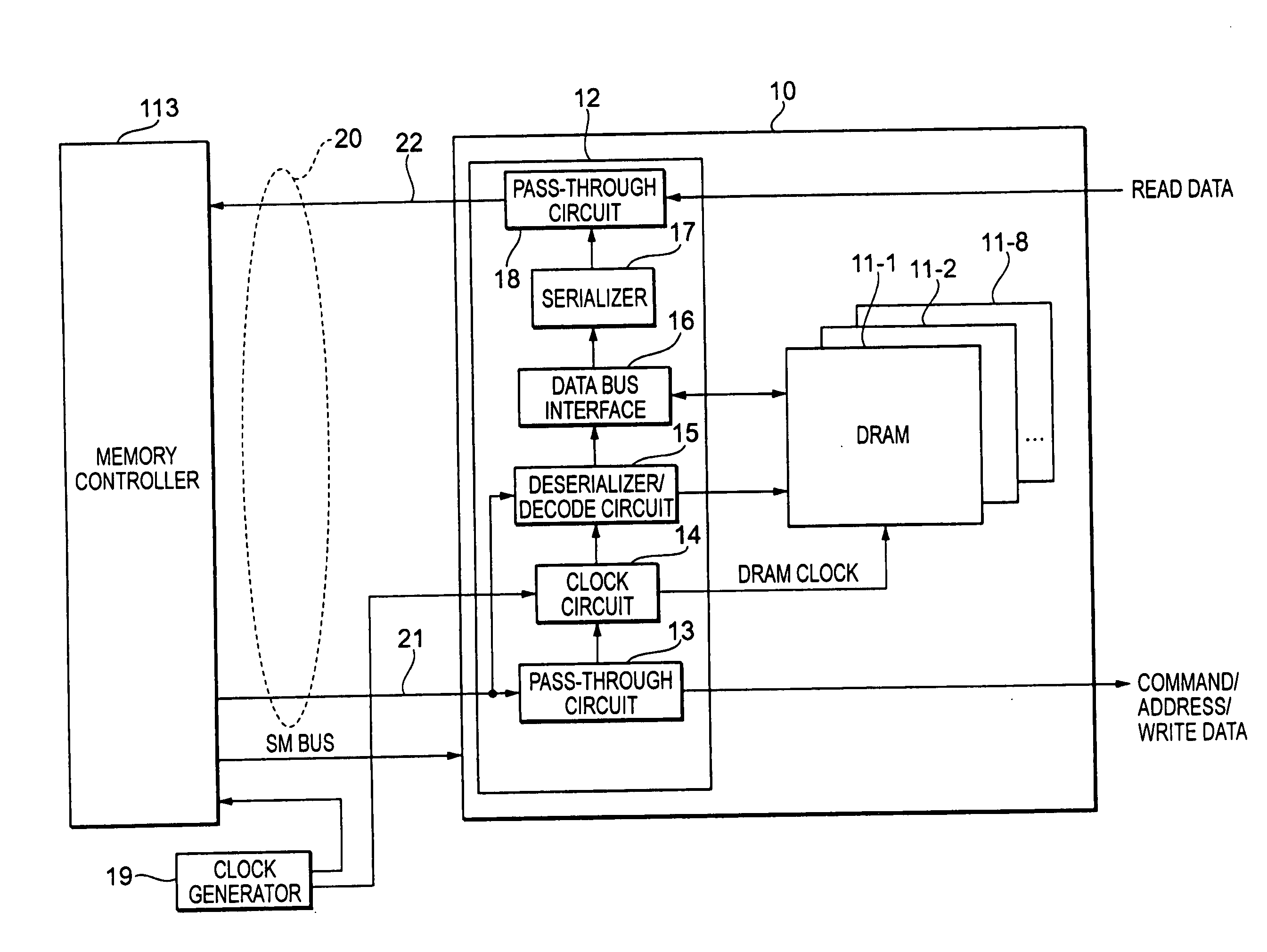
[0009] Accordingly, an object of the present invention is to provide a storage device control apparatus which serves as a storage device for temporarily storing data, while being capable of ensuring a sufficient reliability even when a memory controller and memory modules are connected by a serial interface.
[0013] Another configuration of the memory system comprises, for example, first systematic and second systematic memory-module groups, each composed of a plurality of memory modules, a memory controller for controlling memory access to the memory modules belonging to each of the first and second systematic memory-module groups, and a control circuit for controlling the switching of a memory access path from the memory controller to each memory module. A command, an address and data are serially transmitted from the memory controller to each of the memory modules, each of the memory modules having a plurality of memory elements and a plurality of buffer units. Each of the buffer units receives and interprets the command serially transmitted from the memory controller, controls the memory access to each of the memory elements from the memory controller, and simultaneously converts the serially transmitted data into parallel data and transmits the parallel data to each of the memory elements. The memory controller and each of the memory modules are connected to each other by a serial interface such that a first access path for performing a memory access from the memory controller to the memory module belonging to the first systematic memory module group and a second access path for performing a memory access from the memory controller to the memory module belonging to the second systematic memory module group are different from each other. The control circuit writes the same data as the data stored in the first systematic memory module through the first access path to the second systematic memory module through the second access path, when performing a write access from the memory controller to the first systematic memory module. Thereby, by dual writing of the data, the reliability of the memory system can be increased.
[0014] Another configuration of the memory system comprises, for example, a plurality of memory modules and a memory controller for controlling memory access to the plurality of memory modules, in which a command, an address and data are serially transmitted from the memory controller to each of the memory modules, each of the memory modules having a plurality of memory elements and a plurality of buffer units. Each of the buffer units receives and interprets the command serially transmitted from the memory controller, controls the memory access to each of the memory elements from the memory controller, and simultaneously converts the serially transmitted data into parallel data and transmits the parallel data to each of the memory elements. The memory controller comprises first and second memory interface units for loop-connecting with the buffer unit of each of the memory modules through a serial interface signal line. The memory controller can access each of the memory modules by any one of the first and second memory interface units. Thereby, by duplicating the access path such that the memory access can be performed in bi-directions of the loop-shaped serial interface, the reliability of the memory system can be increased.
[0015] Another configuration of the memory system comprises, for example, a plurality of the memory modules and a memory controller for controlling memory access to the plurality of memory modules, wherein a command, an address and data are serially transmitted from the memory controller to each of the memory modules, each of the memory modules having a plurality of memory elements and a plurality of buffer units. Each of the buffer units receives and interprets the command serially transmitted from the memory controller, controls the memory access to each of the memory elements from the memory controller, and simultaneously converts the serially transmitted data into parallel data and transmits the parallel data to each of the memory elements. The memory controller and the buffer unit of each of the memory modules are connected to each other through duplicated serial interface signal lines. Thereby, by duplicating the serial interface signal line serially connecting a memory controller and a memory module, the reliability of the memory system can be increased.

Problems solved by technology

However, there is a limit to transmitting data at high speeds in a parallel interface, and it is difficult to mount the circuit components thereof due to a sharp increase in the wiring density.
However, in the case of using a parallel transmitting method, an error can be corrected by the ECC even if one of the interface signal lines is out of order; however, in the case of using the serial transmitting method, the data cannot be transmitted if an obstacle is generated in the interface signal line.

Method used


Image

  • Storage device control apparatus
  • Storage device control apparatus
  • Storage device control apparatus

Examples


Embodiment Construction

[0045] Structure of Storage System

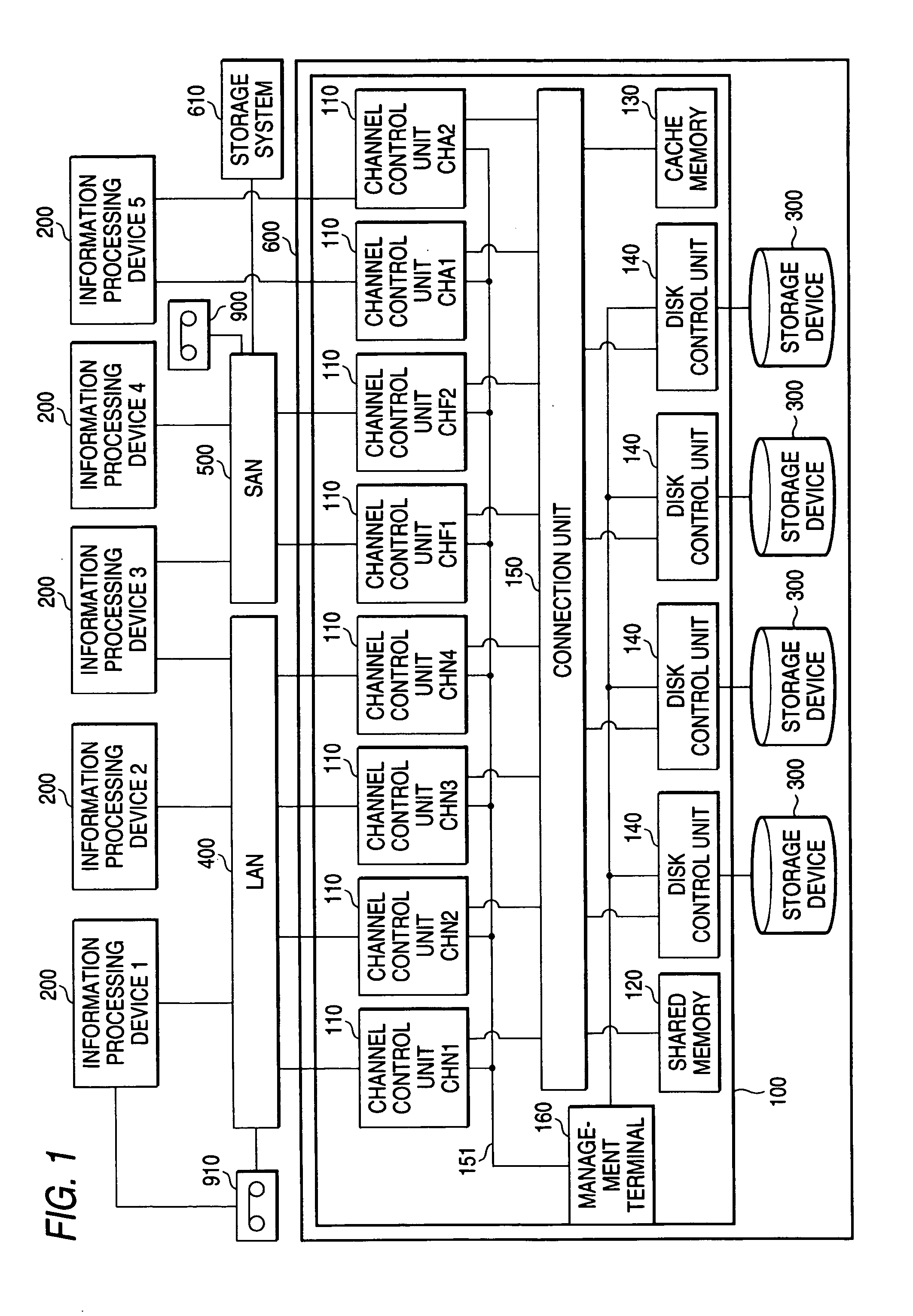
[0046]FIG. 1 illustrates the structure of a storage system 600 according to the present invention. The storage system 600 comprises a plurality of storage devices 300 and a storage device control apparatus 100 for controlling the input to and the output of data from the plurality of the storage devices 300 in response to an input / output request from an information-processing device 200. The information-processing device 200 is a computer apparatus having a CPU, a memory or the like, and it is, for example, a workstation, a main frame computer, or a personal computer. The information-processing device 200 can be comprised by connecting a plurality of the computers with a network. The information-processing device 200 contains an application program operated on an operating system. As examples of an application program, there are an automatic deposit and withdrawal system of the type used by a bank, a seat reservation system for an airplane, and the ...


PUM


Abstract

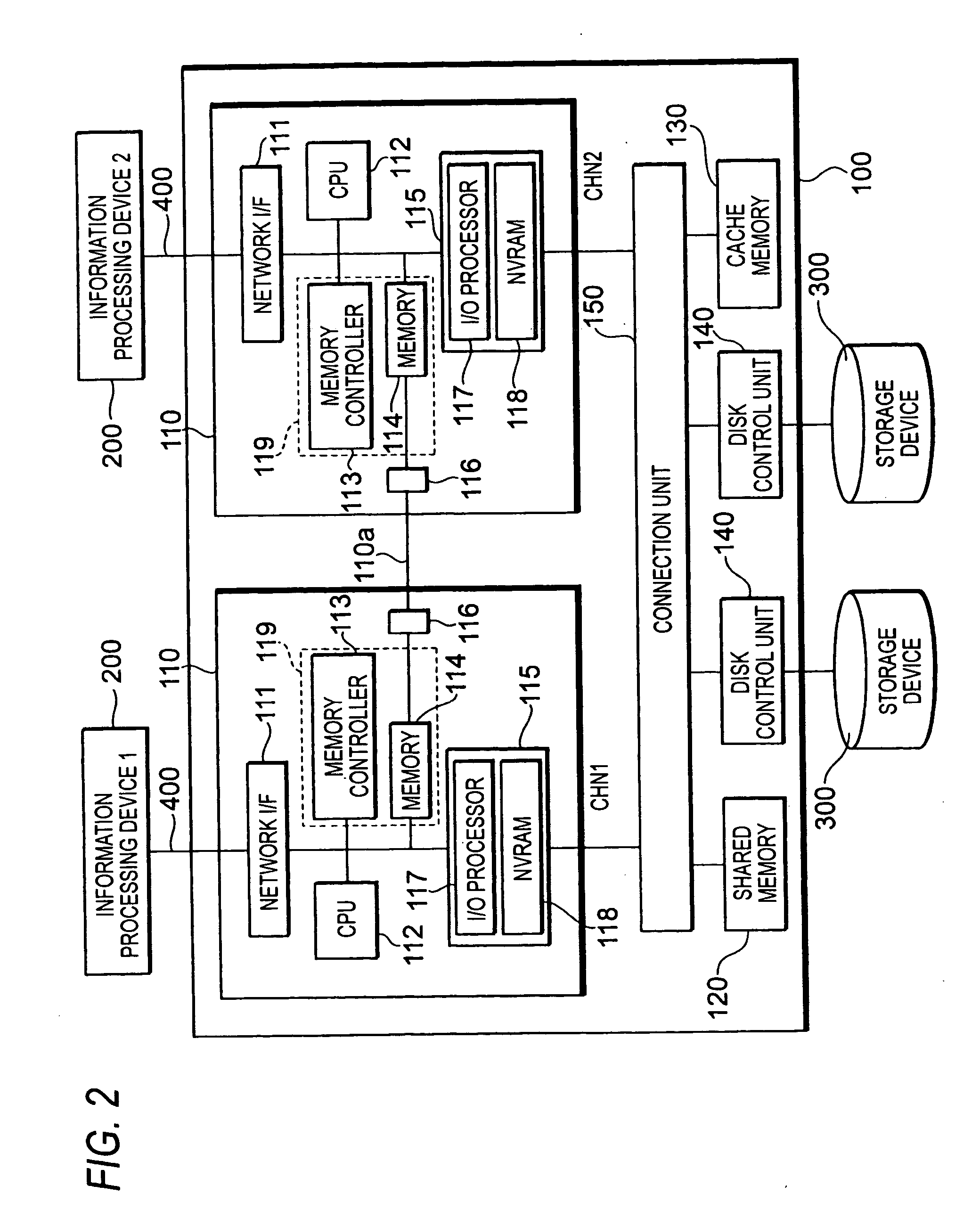
A storage device control apparatus includes a channel control unit for outputting an I / O request for a storage device, having a CPU for receiving a data input / output request in a file unit, an I / O processor for outputting the I / O request corresponding to the data input / output request in the file unit in response to an instruction from the CPU, and a memory system for temporarily storing information required for a file access process of the CPU. The memory system includes a plurality of memory modules and a memory controller for controlling memory access to the plurality of memory modules, a command, an address and data being serially transmitted from the memory controller to each of the memory modules. Each of the memory modules has a plurality of memory elements and a plurality of buffer units. The memory controller and the memory system are connected by duplicated serial interfaces.

Description

CROSS-REFERENCES TO RELATED APPLICATIONS [0001] This application relates to and claims priority from Japanese Patent Application No. 2004-249279, filed on Aug. 27, 2004, the entire disclosure of which is incorporated herein by reference. BACKGROUND OF THE INVENTION [0002] The present invention relates in general to a storage device control apparatus, and, more particularly, to a storage device control apparatus for use in a memory system having a memory module connected to a memory controller by a serial interface to a storage device for storing information based upon access to the storage device control apparatus. [0003] Recently, the amount of data typically processed by a computer system has been rapidly increasing. As a storage system for managing such data, a large scale storage system managed by a RAID (Redundant Arrays of Inexpensive Disks) method for providing a massive storage resource, called a mid-range class or an enterprise class, has been attracting attention. In order...

Claims


Application Information

Patent Timeline
Patent Type & Authority Applications(United States)
IPC IPC(8): G06F12/00
CPCG06F3/0619G06F3/0656G06F11/1666G06F3/0683G06F3/0661
Inventor ILDA, JUNICHIKANAI, HIROKI
Owner HITACHI LTD
Learn More