System and method for simulating an aerial image

a technology of aerial image and simulation method, applied in the field of photolithography, can solve the problems of significant differences between actual and simulated images, and the actual projection system may vary

Active Publication Date: 2006-03-02
APPL MATERIALS ISRAEL LTD
View PDF5 Cites 77 Cited by
  • Summary
  • Abstract
  • Description
  • Claims
  • Application Information

AI Technical Summary

Benefits of technology

[0017] Typically, processing the reference aerial image includes finding the set of expansion functions so as to minimize a difference between the reference aerial image formed using the system and a simulation of the reference aerial image computed using the expansion functions. In disclosed embodiments, finding the expansion functions includes determining a kernel function based on properties of the optical system, and estimating a series of eigenfunctions of the kernel function. In some of these embodiments, finding the expansion functions includes expressing each of the expansion functions as a linear combination of the estimated eigenfunctions multiplied by respective expansion coefficients, and determining the expansion coefficients so as to minimize the difference between the reference aerial image formed using the system and the simulation of the reference aerial image.

Problems solved by technology

Even when the optical system design is precisely known, however, the actual projection system may vary from the design specifications due to factors such as manufacturing tolerances and imprecise alignment of the optical components.
Significant differences between the actual and simulated images can be attributed to defects in the mask under inspection.

Method used


Image

  • System and method for simulating an aerial image
  • System and method for simulating an aerial image
  • System and method for simulating an aerial image

Examples


Embodiment Construction

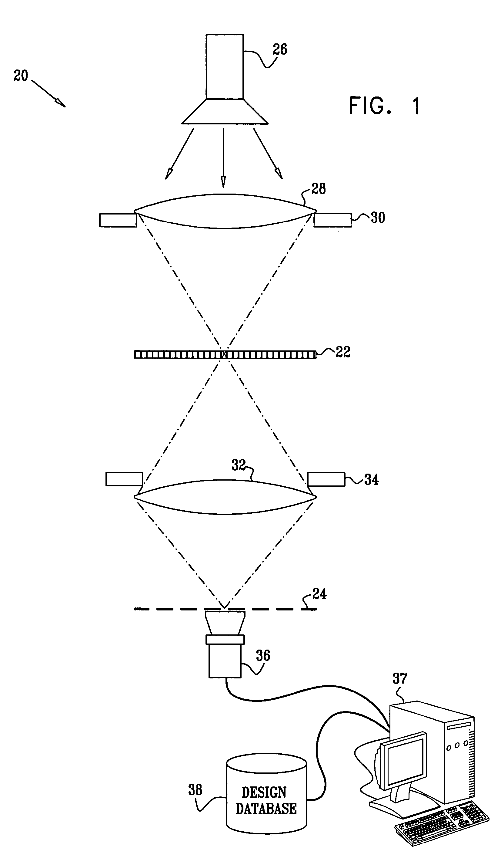
[0034]FIG. 1 is a schematic side view of a system 20 for projection of a mask 22 onto a target plane 24, in accordance with an embodiment of the present invention. Typically, mask 22 embodies a predetermined design for a thin film layer that is to be formed by photolithography on a substrate at plane 24, as is known in the art. The design is characterized by a complex transmission function g({right arrow over (x)}). Alternatively, system 20 may be used in projection of patterns of other types. As noted above, the term “mask” should be understood to comprise substantially any sort of object carrying a pattern that can be projected in this manner onto a target plane. Furthermore, the principles of the present invention may also be applied in projection systems that are based on reflection of radiation from mask 22. For example, these principles may be applied in measuring devices based on optical microscopy systems, which are used in metallurgy and other fields.

[0035] System 20 compr...


PUM


Abstract

A method for generating a simulated aerial image includes forming a reference aerial image of a first mask using an optical system, and capturing and processing the reference aerial image so as to generate a set of expansion functions representative of the optical system. The simulated aerial image of a second mask is then computed by applying the expansion functions to a design of the second mask.

Description

CROSS-REFERENCE TO RELATED APPLICATION [0001] This application is related to another U.S. patent application, filed on even date, entitled “Simulation of Aerial Images,” which is assigned to the assignee of the present patent application and whose disclosure is incorporated herein by reference.FIELD OF THE INVENTION [0002] The present invention relates generally to photolithography, and specifically to simulation of aerial images produced by projecting a mask onto a target surface. BACKGROUND OF THE INVENTION [0003] Photolithography is an essential tool in reproduction of fine patterns on a substrate, and is very widely used in production of microelectronic devices. As the design rules used in such devices become ever finer, mask designers must increasingly resort to reticle enhancement technologies, such as the use of serifs, assist lines and phase shift masks, in order to project the desired pattern onto the device substrate. The aerial image that is actually formed on the substra...

Claims


Application Information

Patent Timeline
Patent Type & Authority Applications(United States)
IPC IPC(8): G06F17/50G21K5/00
CPCG03F1/144G03F1/36G06F17/5009G03F7/70666G03F7/705G03F1/68G06F30/20
Inventor SCHWARZBAND, ISHAI
Owner APPL MATERIALS ISRAEL LTD
Why Eureka
Try Eureka