
Vise carriage and support mechanism

a support mechanism and vise carriage technology, applied in the field of material feed systems, can solve the problems of limiting the movement range of the vise carriage to less than half the length of the table, the problem of affecting the stability of the vise carriage, and the difficulty of adjusting the suppor

Active Publication Date: 2006-03-09
MARVEL MFG
View PDF13 Cites 4 Cited by
  • Summary
  • Abstract
  • Description
  • Claims
  • Application Information

AI Technical Summary

Benefits of technology

[0004] It is also well known to use a series of rollers for supporting and allowing free movement of material on a roller table. Generally, a series of fixed rollers are provided and are located equally spaced along the length of the table. Such a configuration would require the vise carriage to have an overhead support tying both sides of the vise together in order to allow the vise carriage to freely pass over the rollers. An overhead support, however, is problematic because it prevents the loading of material from above the vise.
[0007] Thus, there is a need for increasing the stroke of a vise carriage when used in combination with a hydraulic cylinder and piston rod. Also, there is a need for improved support for a piece of material being moved by a vise carriage. It is therefore a primary object of the invention described and claimed herein to provide a mechanism to multiply the stroke of a hydraulic cylinder and piston rod to provide a wide range of movement for a movable vise carriage. It is a further object of the inventions described and claimed herein to provide a movable support which moves smoothly in concert with the vise carriage for minimizing the unsupported length of material being moved by the vise carriage. It is another object of the inventions describe and claimed herein to provide means for material support for a roller table having a vise carriage without an overhead support. It is another object of the inventions described and claimed herein to provide a mechanism to effectuate concurrent movement of the roller support and vise carriage.
[0009] The preferred means for controlling the movement of the roller supports and the vise carriage is a mechanism comprised of a hydraulic cylinder and piston rod used in combination with a rack-and-pinion system to provide a doubling effect on the stroke of the hydraulic cylinder. The hydraulic cylinder is fixed to the frame of the table and the piston rod movably extends from the hydraulic cylinder. The rack-and-pinion system has a pinion attached to the distal end of the piston rod and has two racks, one of which is fixed to the frame of the machine while the other is attached to the movable vise carriage. The two racks are located opposite each other along a diameter of the pinion and are parallel to the length of the machine (parallel to the direction of material movement). In a typical rack and pinion system, the pinion is stationary and is powered either by a hand crank or a servomotor. However, in the present invention, the pinion moves laterally (because it is attached to the distal end of the piston rod), while simultaneously engaging with the rack which is fixed to the frame and engaging with the rack which is attached to the movable vise carriage. This configuration effectively causes the movable vise carriage to move twice the distance and velocity of the piston rod. This configuration allows for a doubling of the stroke of the hydraulic cylinder and piston rod; i.e., the range of movement of the movable vise carriage is twice the stroke of the piston rod. The movable support is fixed to the pinion and the piston rod and, thus, will move half at half the velocity and distance as the movable vise carriage.

Problems solved by technology

There are some drawbacks with the currently known means of effectuating movement of a vise carriage.
For example, when a hydraulic cylinder and piston rod are used, the vise carriage's range of movement is limited to the stroke of the hydraulic cylinder, effectively limiting the range of movement of the vise carriage to less than half the length of the table.
An overhead support, however, is problematic because it prevents the loading of material from above the vise.
However, those in the industry have experienced problems with shorter pieces of material falling into the open area between the roller supports which are attached to the vise carriage and the adjacent roller supports which are attached to the frame of the table.
This means of support is also not preferable because the operation of the roller support is not smooth; the roller support is impacted or jerked by the vise carriage when it begins to move.

Method used


Image

  • Vise carriage and support mechanism
  • Vise carriage and support mechanism
  • Vise carriage and support mechanism

Examples


Embodiment Construction

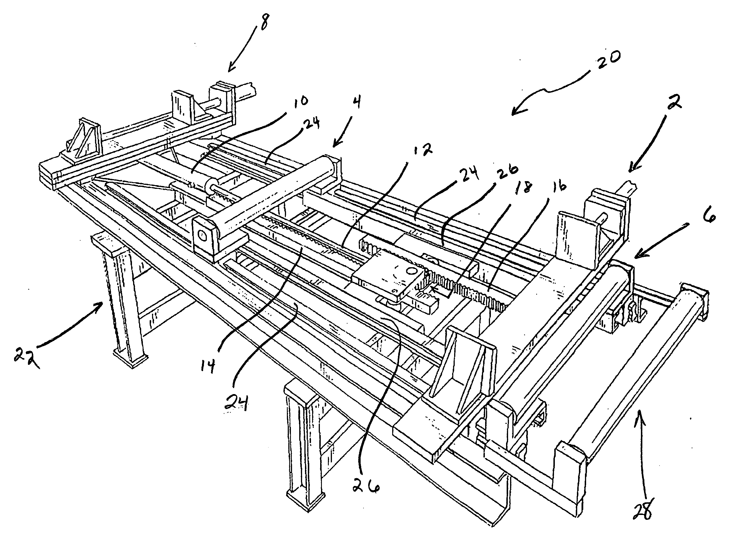
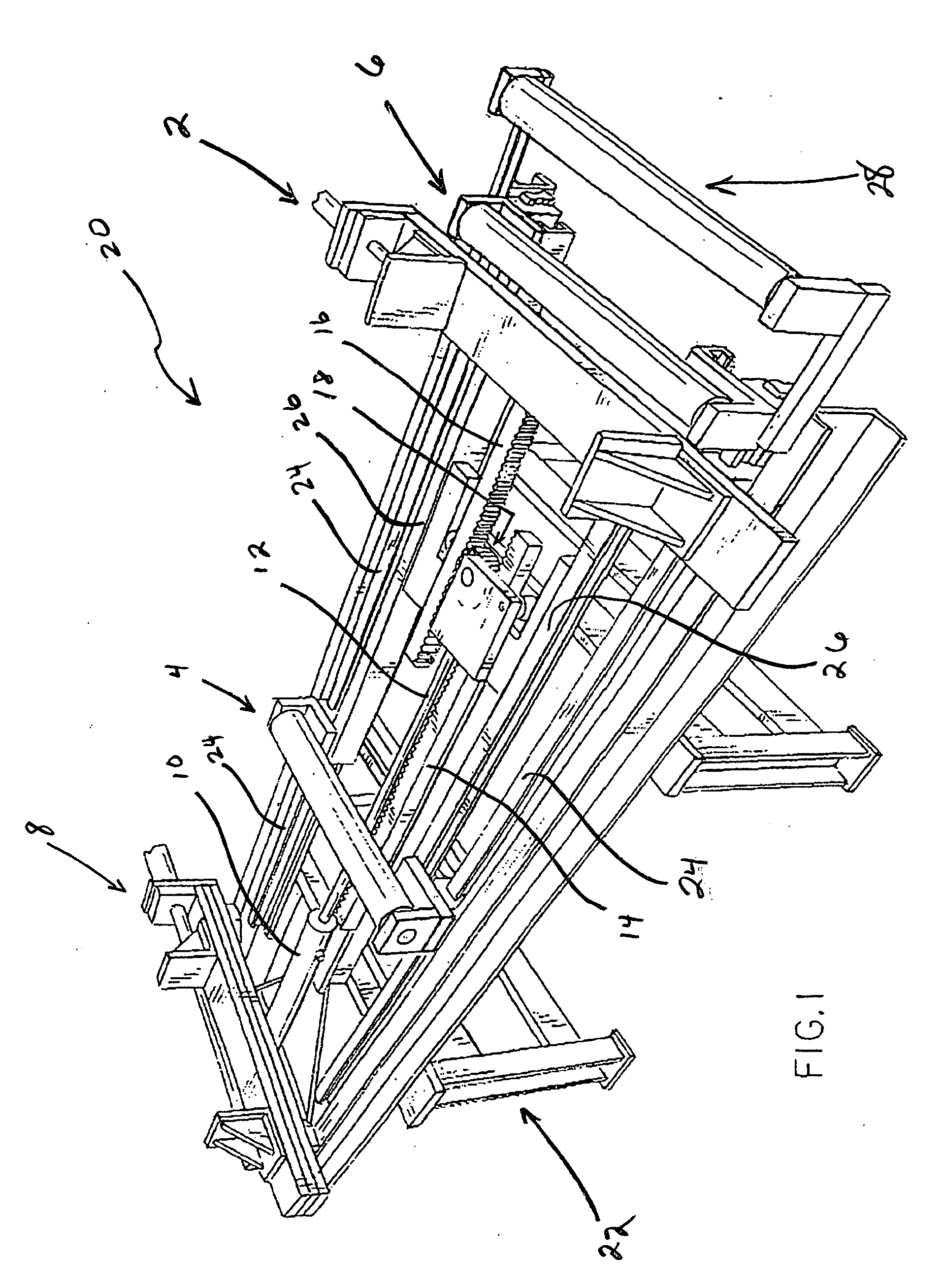
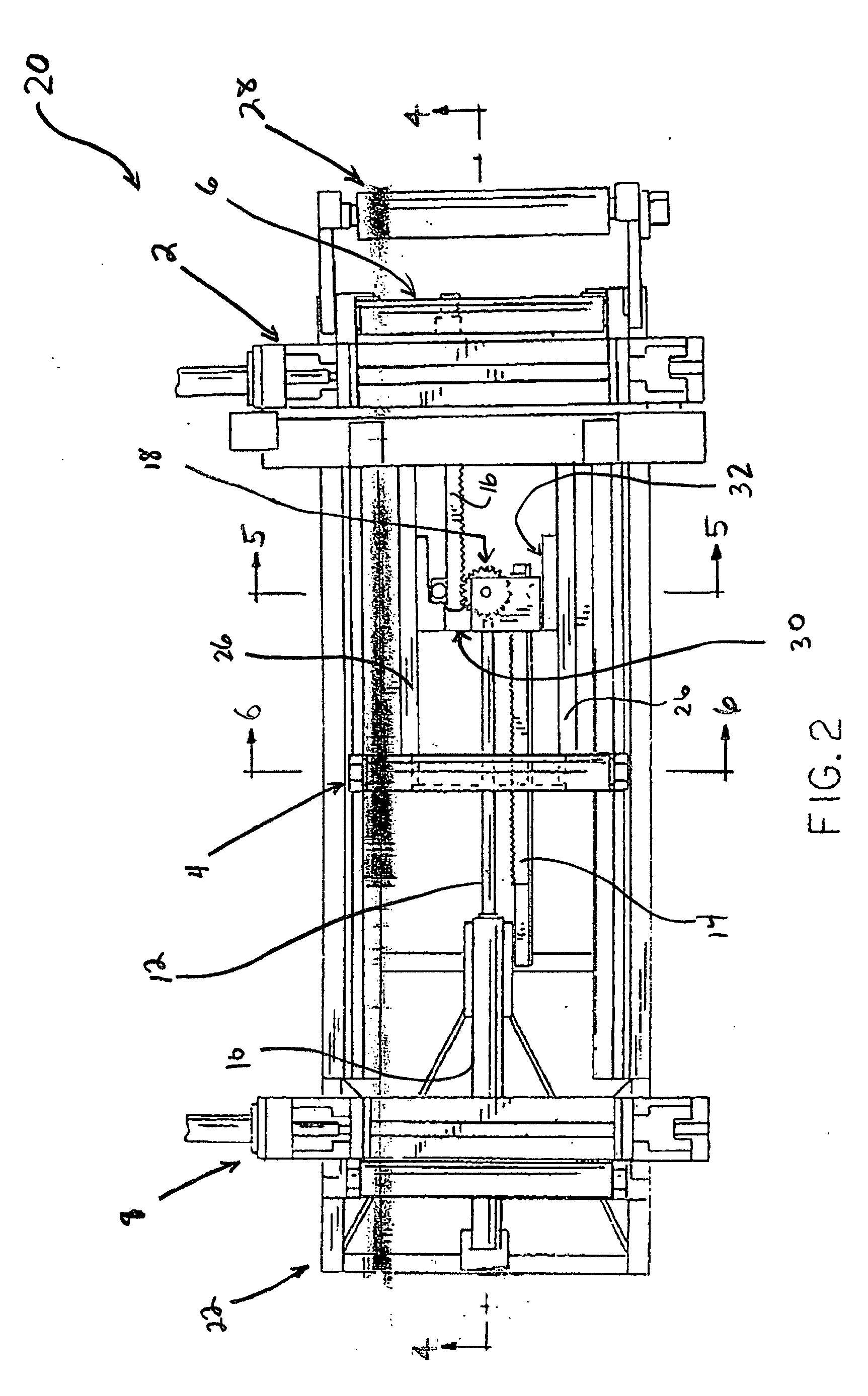
[0021] Referring first to FIG. 1, a perspective view of a preferred embodiment of a roller table 20, according to the present inventions described herein, is shown. Roller tables 20 are generally used in conjunction with cutting machines to feed, support and position material, although the present invention can be used in other applications which require a material feed system. The preferred embodiment of the roller table 20 includes a movable vise carriage 2 and a pair of movable roller supports 4 and 6, all of which are disposed on a pair of rails 24. The pair of rails 24 are fixed to the frame 22 of the roller table 20, and run along the length of the roller table 20 to define the range of movement for the vise carriage 2 and the movable roller supports 4 and 6. The first movable roller support 4 is preferably located approximately at the midpoint of the span between the movable vise carriage 2 and a stationary vise 8, which is fixed to the frame 22 of the roller table 20. The se...


PUM

PropertyMeasurementUnit
Lengthaaaaaaaaaa
Ratioaaaaaaaaaa
Distanceaaaaaaaaaa

Abstract

A roller table with a vise carriage and movable roller supports for moving, positioning, and supporting material. In the preferred embodiment, a hydraulic cylinder and piston rod are used in conjunction with a rack and pinion system such that there is a doubling effect on the piston rod stroke for effectuating differential positioning of two movable roller supports and the vise carriage. One movable roller support is disposed at approximately the midpoint between the vise carriage and a fixed vise. For a given displacement of the vise carriage, the movable roller support travels half as far so as to remain essentially at the midpoint of the span. The second movable roller support is disposed on the other side of the vise carriage, more or less at the midpoint between the vise carriage and a fixed roller support. The second movable roller support is integral with the first movable roller support and, thus, also travels half as far as the vise carriage for a given displacement so as to remain essentially at the midpoint between the vise carriage and the fixed roller.

Description

BACKGROUND AND SUMMARY OF THE INVENTION [0001] The present invention relates generally to a material feed system for a cutting machine, and relates specifically to the simultaneous movement of a vise carriage and moveable support rollers for moving, positioning, and supporting material on a roller table. [0002] It is well known to use a roller table having a vise carriage, also referred to as a shuttle vise, for movement of material to and from a cutting machine. For effectuating movement of the vise carriage, it is known in the art to use belts and pulleys, drive screws and drive sleeves, hydraulic cylinders and piston rods, or racks and pinions, as described in U.S. Pat. Nos. 4,241,630 and 6,698,159. Specifically, U.S. Pat. No. 4,241,630 teaches how to move a vise carriage by mounting a hydraulic cylinder to the frame of the roller table and attaching the distal end of the piston rod to the vise carriage. It is also known in the art to use a rack-and-pinion system to control movem...

Claims


Application Information

Patent Timeline
IPC IPC(8): B26D1/00
CPCB23D47/042Y10T83/6563Y10T83/6649Y10T83/929
Inventor JOURDAN, JAMES K.
Owner MARVEL MFG
Learn More