Heat exchanger and method of manufacturing the same

a technology of heat exchanger and header, which is applied in the direction of indirect heat exchanger, refrigeration components, light and heating apparatus, etc., can solve the problems of difficult machine openings in headers, high process cost, and inability to meet the requirements of the process, so as to shorten the passing time and the distance of the fluid inside the header. , the effect of reducing the length of the header

Inactive Publication Date: 2006-03-09
DENSO AIRCOOL CORP
View PDF15 Cites 25 Cited by
  • Summary
  • Abstract
  • Description
  • Claims
  • Application Information

AI Technical Summary

Benefits of technology

[0012] The present invention provides a heat exchanger including: a heat exchange section in which a plurality of flat tubes are arranged substantially in parallel in a minor axis direction at first intervals with fins disposed between the flat tubes; and a header to which at least some flat tubes out of the plurality of flat tubes are connected in a state where the at least some flat tubes are bent in the minor axis direction outside the heat exchange section and end parts of the at least some flat tubes are arranged substantially in parallel at second intervals that are narrower than in the heat exchange section so that the minor axis direction and a central axis direction of the header are the same direction. Conventionally, a header distributes fluid to a plurality of tubes, with the header extending as far as the positions of the tubes subjected to the distribution, but conversely with the present invention, flat tubes are bent and grouped outside the heat exchange section, so that the headers are shortened. Accordingly, in the heat exchanger according to the present invention, the passing time and distance for the fluid inside the header are shortened, so that the effects of factors, such as gravity and the flow state, to the passing fluid inside the header, are lessened and it becomes possible to supply a liquid such as refrigerant to the plurality of flat tubes with a more uniform state and conditions.

Problems solved by technology

If the flat tubes are not disposed radially, the length by which the end parts of the tubes protrude inside the header will change and the angle made between the end parts of the tubes and the inside surface of the header will change depending on the positions at which the tubes are connected, so that even if the header is made shorter, the flow conditions near the openings of the respective tubes will vary greatly and the state and conditions of the fluid supplied to the respective tubes will be susceptible to change.
To attach the flat tubes to the header radially, it becomes difficult to machine the openings in the header and the process requires many man-hours.
Since the bending angle of the flat tubes is determined one pipe at a time, designing also takes time and there is an increased burden for machining and assembly, making this construction unsuited to mass production.
In addition, since the attachment angles of the respective pipes to the header differ, it is not possible to tightly attach the flat tubes together, and as the number of pipes increases, a header with a large diameter becomes necessary.

Method used


Image

  • Heat exchanger and method of manufacturing the same
  • Heat exchanger and method of manufacturing the same
  • Heat exchanger and method of manufacturing the same

Examples


Embodiment Construction

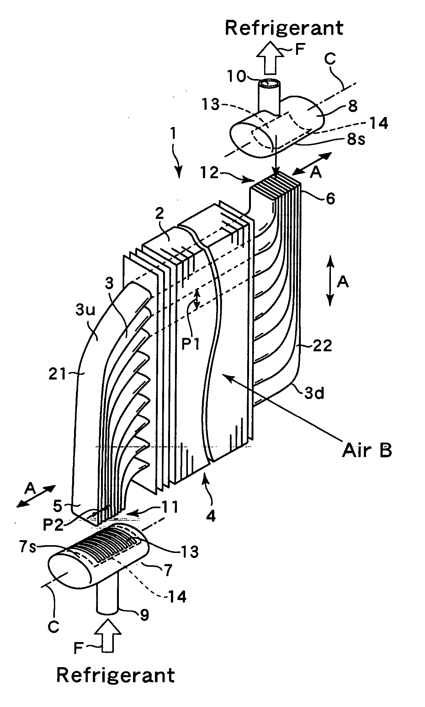
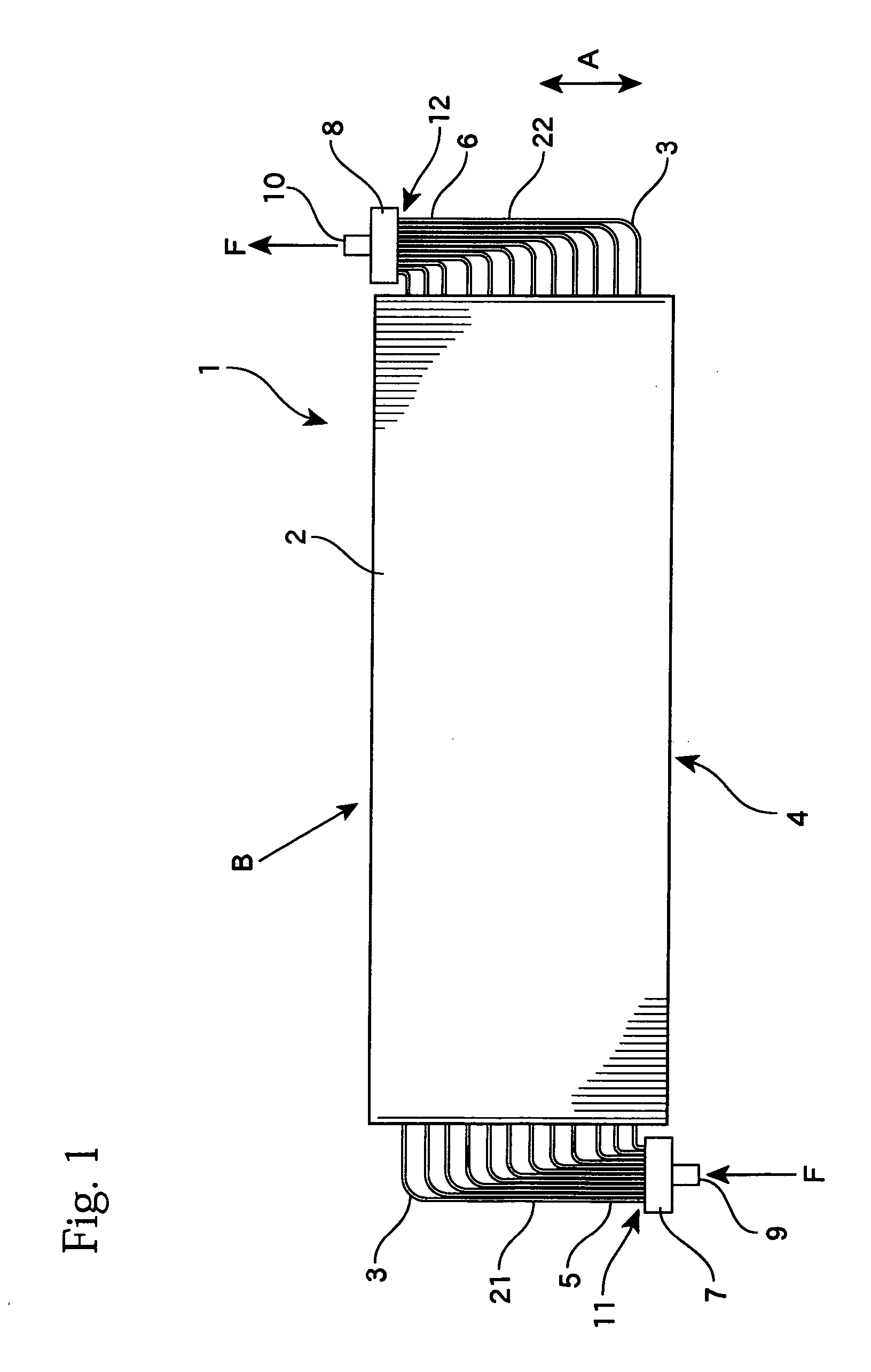
[0044] The present invention will now be described in more detail with reference to the drawings. FIG. 1 schematically shows a heat exchanger according to the present invention. The heat exchanger 1 is a so-called “plate fin-type heat exchanger” and includes a plurality of plate-like fins 2 that are disposed in parallel at fixed intervals and a plurality of flat tubes 3 that pass through and are attached to the fins 2 in parallel, with these parts constructing a heat exchange section (heat exchanging unit) 4. In the heat exchanger 1, both end parts 5 and 6 of the plurality of flat tubes 3 are arranged substantially in parallel at second intervals that are narrower than a first interval (pitch) of the flat tubes 3 inside the heat exchange section 4 and are respectively connected to headers 7 and 8 positioned to the left and the right. A heat exchange medium (hereinafter, “internal fluid”) F such as a refrigerant, heat transfer medium, or the like supplied from a supply opening 9 of t...


PUM


Abstract

There is provided a heat exchanger including: a heat exchange section in which a plurality of flat tubes are arranged substantially in parallel in a minor axis direction at first intervals and in which fins are disposed between the flat tubes; and a header to which at least some flat tubes out of the plurality of flat tubes are connected, in a state where the at least some flat tubes are bent in the minor axis direction outside the heat exchange section and end parts of the at least some flat tubes are arranged substantially in parallel at second intervals that are narrower than in the heat exchange section, so that the minor axis direction and a central axis direction of the header are the same direction. With this heat exchanger, it is possible to distribute fluid to the individual flat tubes with more equal conditions so that the heat exchange efficiency can be increased.

Description

TECHNICAL FIELD [0001] The present invention relates to a heat exchanger used in a refrigeration apparatus, a cooling apparatus or the like, and to a method of manufacturing the same. RELATED ART [0002] Japanese Laid-Open Patent Publication No. 2000-249428 discloses a heat exchanger that uses flat tubes and is to be used in a refrigeration apparatus, a radiator, or the like. Its evaporator includes a plurality of flat tubes and corrugated fins, and is supplied with a refrigerant from a header to which the flat tubes are connected. To optimize the distribution of a liquid refrigerant that flows in, an injector is disposed in the header. [0003] To increase the heat exchange efficiency when the fluid or coolant supplied to the header is distributed to the respective tubes in the heat exchanger, it is important to distribute the fluid equally into the respective tubes. In the evaporator (heat exchanger) 100 in the refrigeration apparatus shown in FIG. 14 includes a plurality of fins 104...

Claims


Application Information

Patent Timeline
Patent Type & Authority Applications(United States)
IPC IPC(8): F28F9/02F28D1/04F28D1/047F28F1/02F28F1/32
CPCF25B39/00F25B39/028F28D1/047F28F1/02F28F9/0275F28F1/32F28F9/02F28F9/0221F28F1/025F25B41/42
Inventor MAEZAWA, TAKAHIDETSUJI, MASANORI
Owner DENSO AIRCOOL CORP
Why Eureka
Try Eureka