Device and method for electrochemical reduction

a technology of electrochemical reduction and device, which is applied in the direction of electrochemical machining apparatus, metal-working apparatus, manufacturing tools, etc., can solve the problems of uneven removal, deviation of the achieved shape from the desired shape of the workpiece, and non-uniform distribution of the removal products of the workpiece in the electrolyte, etc., to achieve the effect of increasing the processing precision of electrochemical reduction

Inactive Publication Date: 2006-03-09
MTU AERO ENGINES GMBH
View PDF7 Cites 2 Cited by
  • Summary
  • Abstract
  • Description
  • Claims
  • Application Information

AI Technical Summary

Benefits of technology

[0018] The coupling in or introduction of the sound waves during the electrochemical reduction advantageously prevents the development of passivation layers on the surface of the workpiece in the area of the reduction gap, as well as influencing of the electromagnetic field between electrode and workpiece due to uneven distribution of the removal products in the electrolyte. This measure increases the processing precision of the electrochemical reduction, and in particular enables processing using reduction gaps having a smaller gap dimension than customary in the past.
[0019] According to an advantageous embodiment of the present invention, the sound waves of the sonotrode are coupled at least indirectly into the electrolyte, and the flow of electrolyte through the reduction gap is produced. At the same time the introduced sound waves, in particular ultrasonic waves, may support the flow of the electrolyte through the reduction gap, in particular actively, and produce a pump effect. The sound waves generated by the sonotrode are in particular ultrasonic waves, it preferably being ensured that no standing waves are formed in the electrolyte in the area of the reduction gap. It corresponds here to an advantageous embodiment if the sound waves are coupled into the electrolyte indirectly through the workpiece or the electrode. Coupling the sound waves from the sonotrode via the workpiece has the advantage in particular that the sound waves pass through the workpiece, and that the development of passivation layers in the area of the surface of the workpiece is therefore prevented in the processing area, i.e., in the reduction gap, in an especially advantageous way.

Problems solved by technology

Furthermore, in reduction processes, non-uniform distributions of the removal products of the workpiece in the electrolyte may occur, especially when the reduction gap between workpiece and electrode is very small, as is necessary to achieve high precision of the surface processing and the shape stability.
This may result in uneven removal, and thus in deviations of the achieved shape from the desired shape of the workpiece after the processing.
Furthermore, because of the deposition of removal products in the reduction gap, occasional disruptions of processing may also occur due to short circuit currents, which result in unwanted damage to the shape of the electrode and consequent processing imprecisions, but also to damage to the workpiece in the vicinity of the short circuit current.

Method used


Image

  • Device and method for electrochemical reduction
  • Device and method for electrochemical reduction

Examples


Embodiment Construction

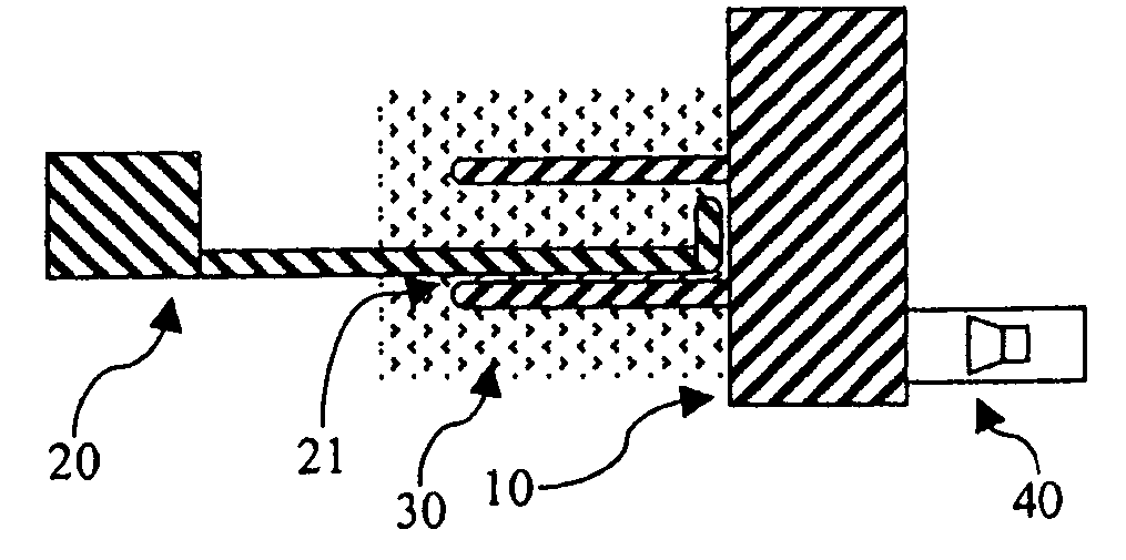
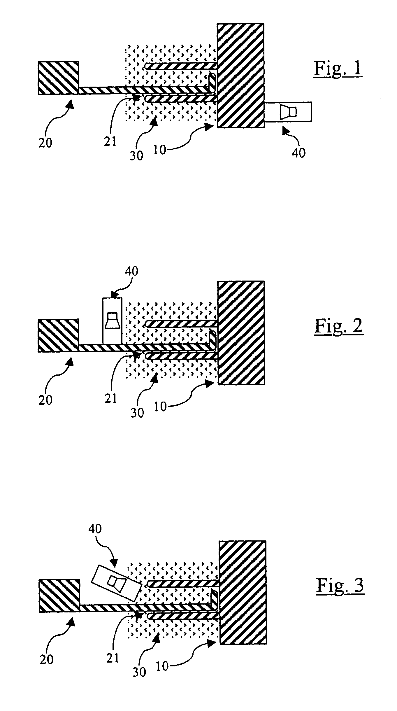
[0024]FIGS. 1 through 3 show a schematic representation of devices according to the present invention for electrochemical reduction using a sonotrode to introduce sound waves, the sonotrode being positioned in different areas.

[0025]FIG. 1 shows a schematic arrangement in which the sonotrode is positioned in the processing area of the workpiece; FIG. 2 shows an arrangement in which the sonotrode is positioned in the electrode; and FIG. 3 shows a schematic representation of an exemplary embodiment in which the sonotrode couples the sound waves directly into the electrolyte.

[0026] All three figures show a workpiece 10 which is processed by electrochemical reduction. To this end electrode 20 is guided relative to the workpiece, while a reduction gap 21 is maintained with the smallest possible gap dimension between electrode 20 and workpiece 10. In addition, there is an electrolyte 30 at least in the area of reduction gap 21. To carry out the reduction process, a current flows between ...


PUM

PropertyMeasurementUnit
gap dimensionaaaaaaaaaa
currentaaaaaaaaaa
frequencyaaaaaaaaaa

Abstract

A device for electrochemical reduction of a workpiece (10) includes a workpiece (10), an electrode (20), and an electrolyte (30), which is located between electrode (20) and workpiece (10). The electrode (20) is moved close to the workpiece (10) with a small gap dimension (21), and a processing of the workpiece (10) occurs through a flow of current between electrode (20) and workpiece (10) through the electrolyte (30). In addition, a sonotrode is positioned to introduce sound waves.

Description

[0001] Priority is claimed to German Patent Application DE 10 2004 041 780.8, filed Aug. 28, 2004, the entire disclosure of which is incorporated by reference herein. FIELD OF THE INVENTION [0002] The present invention relates to a method for electrochemical reduction of a workpiece. BACKGROUND [0003] For reduction, a workpiece on which a shaping or surface processing is to be undertaken by removal of material, at least in its area for processing, is brought into the environment of an electrolyte and the workpiece is placed in electrical contact with the ground. An electrode is brought into proximity with the workpiece and is shaped according to the necessary processing. A current flows through the electrolyte which is located in the intermediate space between the electrode and the workpiece being processed. An electrochemical removal of material from the surface of the workpiece occurs between this electrolyte and the workpiece due to the flow of current. [0004] Depending on the wo...

Claims


Application Information

Patent Timeline
Patent Type & Authority Applications(United States)
IPC IPC(8): C25D5/20
CPCB23H7/38B23H3/00
Inventor BAYER, ERWINBUSSMANN, MARTINKRAENZLER, THOMASPLATZ, ALBINSTEINWANDEL, JUERGEN
Owner MTU AERO ENGINES GMBH
Why Eureka
Try Eureka