
Control method of generator

a control method and technology of a generator, applied in the control of electric generators, control systems, electrical apparatus, etc., can solve the problems of power generation efficiency decline, regenerative energy cannot be secured, etc., and achieve the effect of reducing current rate, increasing power generation rate, and reducing current ra

Active Publication Date: 2006-03-09
MITSUBA CORP
View PDF8 Cites 9 Cited by
  • Summary
  • Abstract
  • Description
  • Claims
  • Application Information

AI Technical Summary

Benefits of technology

The present invention relates to a controlling method for a generator that improves power generating efficiency. The method involves executing a reflux mode after a supply mode to set both ends of the winding to the same potential, followed by a regenerative mode for recovering the electromotive force generated in the winding to the power source. The method also includes an alternating mode for alternating between the supply mode and the reflux mode, and a second alternating mode for alternating between the reflux mode and the regenerative mode. The method suppresses the brake force and increases the current value in the reflux mode, resulting in improved power generating efficiency. The generator is controlled by a switching circuit with a switching element and a diode connected to both ends of the winding, and the switching element is PWM controlled to execute the alternating modes. The method also includes controlling the voltage of the power source and the continuation time of the alternating modes to optimize power generation.

Problems solved by technology

When the increase in the current at the reflux mode time is not sufficient, the amount of the regenerative energy in the regenerative mode cannot be secured, and the power generating efficiency decreases.

Method used


Image

  • Control method of generator
  • Control method of generator
  • Control method of generator

Examples


embodiment 1

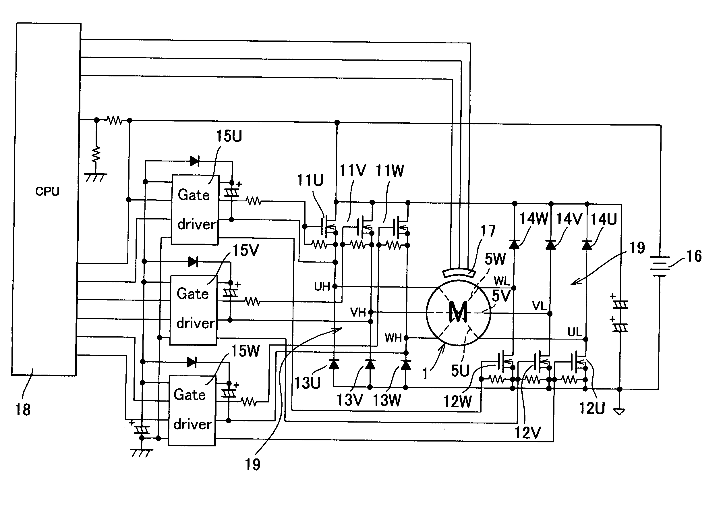
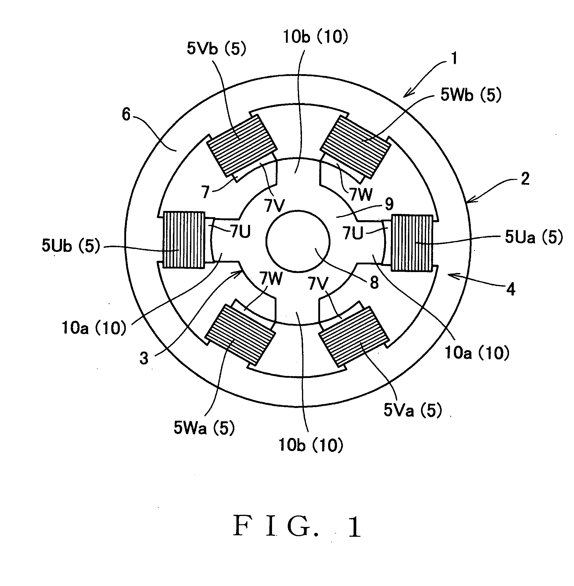
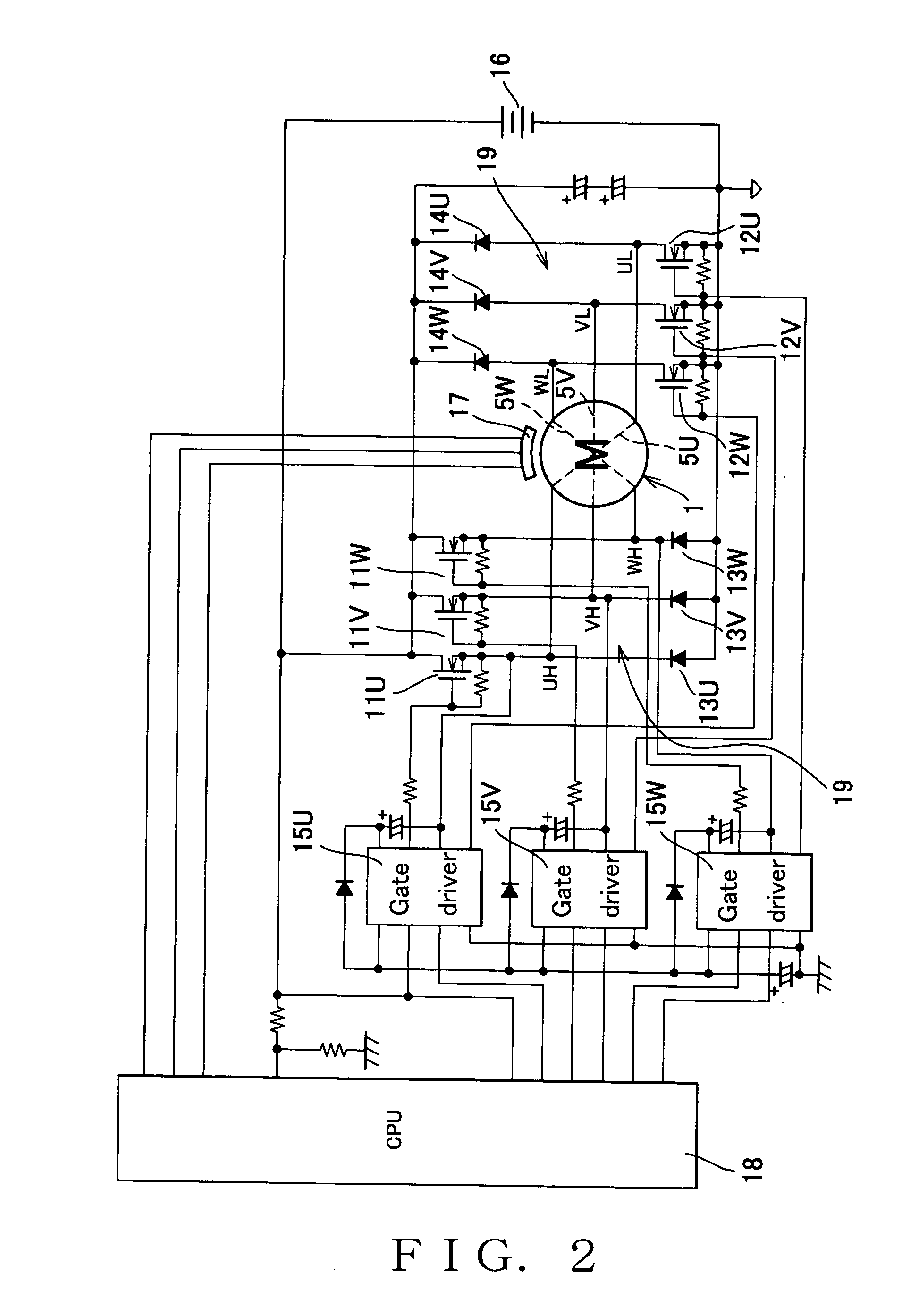
[0026] Now, the embodiments of the present invention will be described in detail with reference to the accompanying drawings. FIG. 1 is an explanatory view showing a construction of a generator applied with a controlling method of an embodiment 1 of the present invention. A generator 1 of FIG. 1 has a structure similar to a so-called SR motor, and comprises a stator 2, and a rotor 3 that is rotatably arranged inside the stator 2. The stator 2 is contained in a housing (not shown). The generator 1 is driven, for example, by an automobile engine. In this case, the rotor 3 is coupled to a crankshaft of the engine. The generator 1 of this embodiment is an inner rotor type, but may be an outer rotor type in which the positional relationship between the stator and the rotor is opposite.

[0027] The stator 2 has a stator core 4 and a plurality of windings 5. The stator core 4 is formed by laminating a plurality of magnetic steel sheets, and fixed in the housing. The stator core 4 has a cyli...

embodiment 2

[0044] In the meantime, in order to increase the power generation rate in a control method as in the embodiment 1, it is necessary to increase a winding current value in the alternating mode. To this end, there arises a need to raise the ON duty ratio under the PWM control in an alternating mode time or to lengthen the energizing time. However, when the winding current value in the alternating mode time is increased, there is a problem that the current value in the reflux mode executed after the alternating mode excessively increases. That is, as shown in FIG. 5, the maximum value imax of the winding current value i becomes large. If the winding current value i excessively increases, a load on the power device is increased, and hence elements of large capacity must be used, and thereby to increase the cost.

[0045] In this case, as in the above-mentioned Japanese Patent Application Laid-Open Publication No. 2001-78490, when the reflux mode and the regenerative mode are switched while...

embodiment 3

[0060] Then, as the embodiment 3, the case that starting timing of the first alternating mode C1 is advanced from a position where the inductance L becomes the maximum value Lmax, will be described. When the control as shown in FIG. 5 is performed, a measure that the executing time Td of the alternating mode is increased, times of a reflux mode and a regenerative mode are relatively reduced, and the maximum current value imax is suppressed, is considered. However, when such a measure is adopted, as the times of the reflux mode and the regenerative mode decrease, there is a possibility that a sufficient amount of power generation cannot be obtained.

[0061] Then, starting timing of the alternating mode is advanced to increase an amount of current to a certain degree at the reflux mode starting time after the alternating mode. That is, a control state of advancing an angle may be considered. Particularly, since the winding current becomes an inductance load, even if the first alternati...


PUM


Abstract

When drive control of a generator is performed, PWM control of a switching circuit comprising an FET and a diode connected to the opposite ends of a winding is performed. In the vicinity of a moment in time Lmax where the winding has a maximum inductance L, an alternating mode for repeating a supply mode and a reflux mode alternately is performed through PWM control. After the alternating mode is performed, the reflux mode is performed temporarily in order to increase the quantity of current and then a regenerative mode is performed. The regenerative mode is performed by increasing the current level as much as possible when the reflux mode is started while suppressing the brake force of the rotor in the alternating mode. From a position advancing in angle by a time Tah from the a moment in time Lmax where the winding has a maximum inductance L, a first alternating mode C1 for repeating the supply mode P and the reflux mode Q alternately is performed. After the first alternating mode C1 is performed, a second alternating mode C2 for repeating the reflux mode Q and the regenerative mode R alternately is performed.

Description

TECHNICAL FIELD [0001] The present invention relates to a controlling method of a generator which has an SR motor (Switched Reluctance Motor) structure. BACKGROUND ART [0002] Recently, in an electric automobile or a so-called hybrid car in which a motor and an engine are commonly used, it has been discussed not to use an expensive permanent magnet, but to use an SR motor that has a simple and rigid structure, and excels in a high speed rotation and an environmental resistance. Generally, the SR motor has a construction that a rotor made of magnetic steel sheet is disposed rotatably coaxially with a stator inside the stator in which a coil is wound around. Salient poles projecting inward are formed on an inner peripheral side of the stator, and a coil is wound around on this salient pole to form a winding. Salient poles projecting outward are formed radially on an outer periphery of the rotor, and adapted to approach, oppose and separate from the salient poles of the stator in associ...

Claims


Application Information

Patent Timeline
Patent Type & Authority Applications(United States)
IPC IPC(8): H02P9/00H02P9/40H02P25/08
CPCH02P9/40H02P2101/45H02P25/085H02P25/092
Inventor SASAKI, KOJI
Owner MITSUBA CORP
Learn More