Controllable amplifier circuit with a variable discrete-value gain, use of the amplifier circuit and method for operation of an amplifier whose gain can be adjusted in discrete values

a controllable amplifier and discrete value technology, applied in the direction of amplification control details, gain control, analog signal digital control, etc., can solve the problems of increased bit error rate, high input value, downstream circuit damage, etc., and achieve the effect of little susceptibility to errors

Inactive Publication Date: 2006-03-09
INTEL CORP
View PDF6 Cites 6 Cited by
  • Summary
  • Abstract
  • Description
  • Claims
  • Application Information

AI Technical Summary

Benefits of technology

[0013] Signal processing relating to gain variation is thus carried out both by means of single-ended signals and push-pull signals. In one embodiment of the amplifier circuit a first control block is configured for single-ended signal processing, and a second control block is configured for push-pull signal processing, allowing a soft transition between two different gain levels or gain factors during a switching process, or a change in the gain of the at least one third amplifier stage.
[0014] The push-pull signal processing prevents a signal to be transmitted being at an excessive level during a switching process of the at least one third amplifier stage with a concurrent switching process of the at least one first and second amplifier stage, since the switching signals which are derived from the push-pull signal for the amplifier stages have symmetrical characteristics and thus have little susceptibility to errors.

Problems solved by technology

Such an excessive signal level leads to an amplitude error and a phase error in the signal to be transmitted, and thus increases the bit error rate.
Furthermore, downstream circuits can also be damaged by the high input value.

Method used


Image

  • Controllable amplifier circuit with a variable discrete-value gain, use of the amplifier circuit and method for operation of an amplifier whose gain can be adjusted in discrete values
  • Controllable amplifier circuit with a variable discrete-value gain, use of the amplifier circuit and method for operation of an amplifier whose gain can be adjusted in discrete values
  • Controllable amplifier circuit with a variable discrete-value gain, use of the amplifier circuit and method for operation of an amplifier whose gain can be adjusted in discrete values

Examples


Embodiment Construction

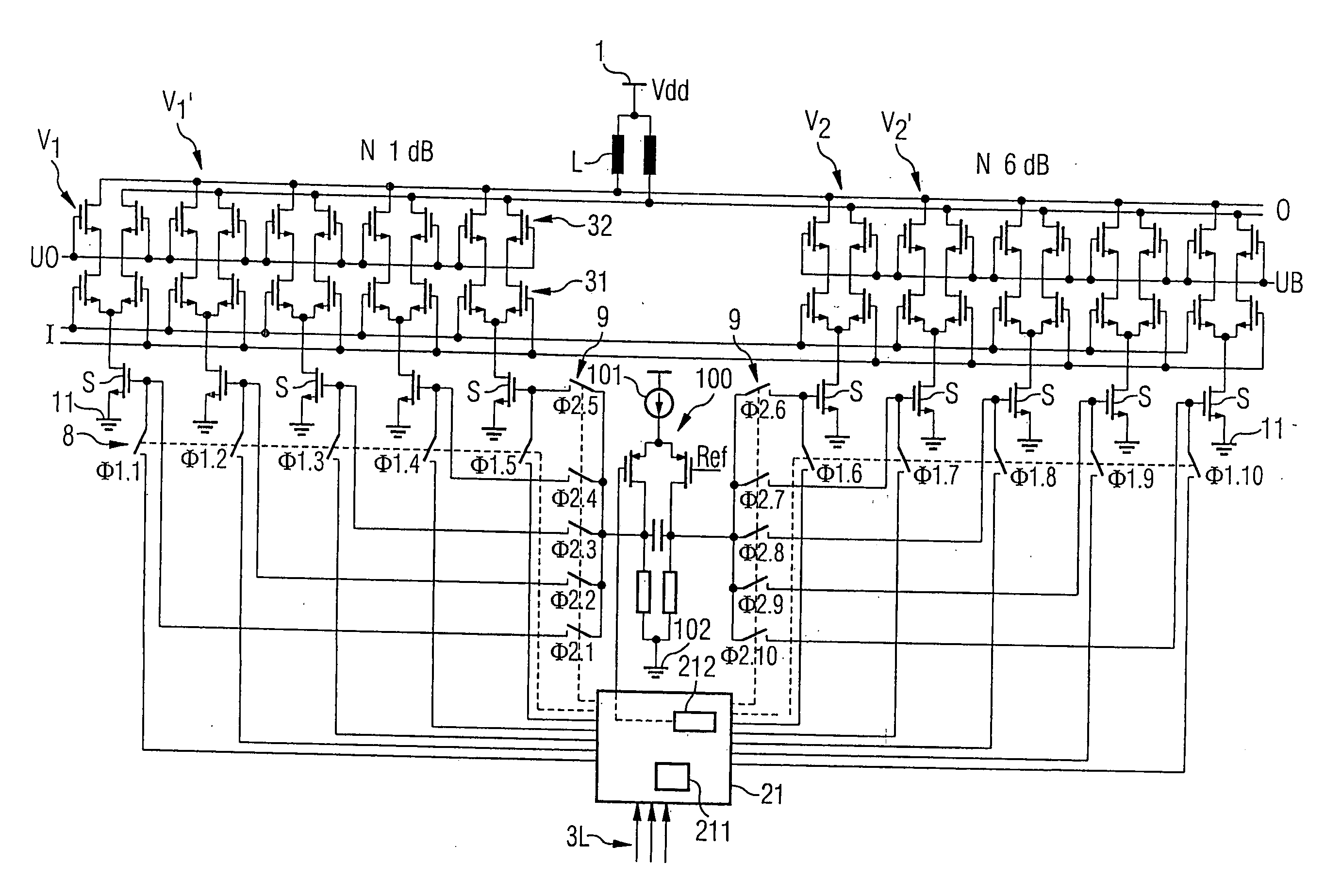
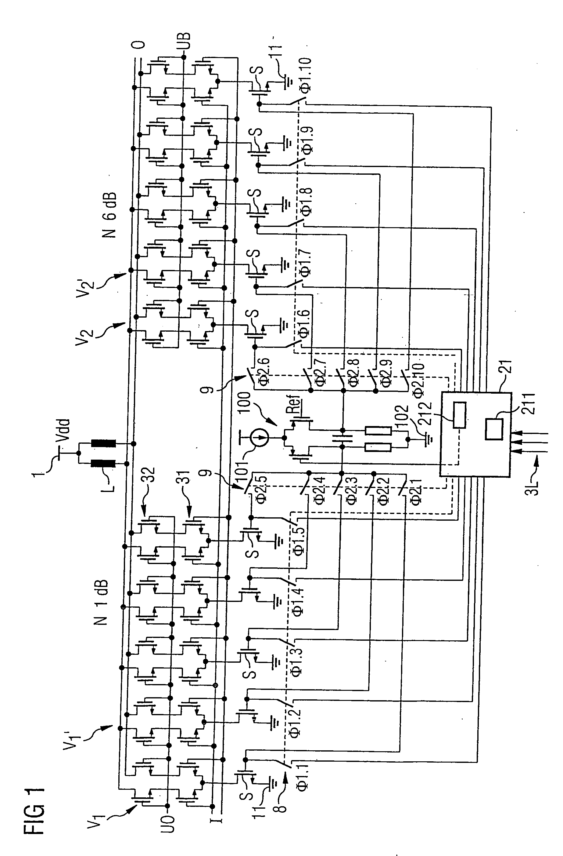
[0033]FIG. 1 shows an amplifier circuit as can be used, by way of example, in a programmable amplifier for the WCDMA / UMTS mobile radio standard. The amplifier may be used not only in its own semiconductor body but also together with further components for the transmission path and the reception path in a transceiver chip. The amplifier has an input I and an output O, which are designed as difference signal inputs and difference signal outputs, respectively. Five amplifier stages are connected in parallel between the input I and the output O. Of these, the amplifier stages V1 and V1′ are mentioned in particular for the rest of the description.

[0034] Each amplifier stage is designed with a differential amplifier stage 31, which is followed by a cascode circuit 32. The control inputs of the differential amplifier 31 are coupled to the input I. The control inputs of the two cascode transistors in the cascode circuit 32 are connected to a further input, to which an adjustment signal UB ...


PUM


Abstract

An amplifier circuit is disclosed in which a first amplifier stage and at least one second amplifier stage are each arranged between a signal input and a signal output. These amplifier stages are designed with a first gain factor and with a switching input. The amplifier circuit also has a third amplifier stage with a second gain factor, which is arranged between the signal input and the signal output. A control circuit is coupled to each amplifier stage for gain adjustment. The control circuit has a first control block designed for single-ended signal processing, and a second control block designed for push-pull signal processing. It is designed to supply control signals from the first control block to the amplifier stage when the gain of the first and at least one second amplifier stage is varied, and to supply control signals from the second control block to all of the amplifier stages when the gain of the at least one third amplifier stage is varied.

Description

REFERENCE TO RELATED APPLICATIONS [0001] This application claims the benefit of the priority date of German application DE 10 2004 039 830.5, filed on Aug. 17, 2004, the contents of which are herein incorporated by reference in their entirety. FIELD OF THE INVENTION [0002] The invention relates to an amplifier circuit whose gain can be adjusted in discrete values, and to its use. The invention also relates to a method for operation of an amplifier whose gain can be adjusted in discrete values. BACKGROUND OF THE INVENTION [0003] The introduction of third-generation mobile radio systems requires very precise compliance with power levels of transmitted signals. For example, the UMTS / WCDMA mobile radio standard demands control of the emitted transmission power in order that the plurality of users who are transmitting in one frequency band do not excessively interfere with one another. The power control which is carried out both by the base stations and by the mobile stations is based on...

Claims


Application Information

Patent Timeline
Patent Type & Authority Applications(United States)
IPC IPC(8): H03G3/10
CPCH03G3/001H03G1/0088
Inventor BOOS, ZDRAVKO
Owner INTEL CORP
Why Eureka
Try Eureka