Flat wide-angle lens system

a wide-angle lens and flat technology, applied in the field of optics, can solve the problems of increasing the overall radius and hence the dimensions inconvenient use and storage, and error in the abbreviation, so as to reduce the overall dimension of the lens system, suppress aberration, and reduce the weight of the lens system

Inactive Publication Date: 2006-03-09
MICROALIGN TECH
View PDF8 Cites 48 Cited by
  • Summary
  • Abstract
  • Description
  • Claims
  • Application Information

AI Technical Summary

Benefits of technology

[0021] It is an object of the invention to provide a wide-angle lens system composed of a combination of a microlens array package with a traditional lens that makes it possible to significantly reduce overall dimensions of the lens system, reduce the weight of the lens system, suppress aberration, and create a compact flat high-performance objective with a wide range of applications, e.g., for creation of photo images. Another object is to provide such a system of micro arrays that can be used in conjunction with conventional lens systems and can convert such system into compact wide-angle objectives without introduction of additional optical aberration effects.
[0022] A flat wide-angle lens system of the invention is intended for creating images with extremely wide angle of observation. The wide-angle lens system consists of two main components. The first component comprises an assembly of at least two microlens arrays with the same pitch between the adjacent microlenses and arranged with respect to each other so as to provide afocality. The first component is intended for reduction of the field angle of light incidence onto the objective, while the second component comprises an assembly of conventional spherical or aspherical microlenses that create an image on an image receiver. The aforementioned first component comprises an array of inverted microtelescopes of Galileo or microtelescopes of Kepler with multiplication equal to or different from 1. The outlet aperture of a single unit telescopic cell is made so that spherical aberration can be minimized almost to 0, while field aberrations can be corrected by design parameters of the microlenses. The focal distance of microlenses on the inlet side is shorter than the focal distance of microlenses on the outlet side. A ratio of their focuses (V=F′2 / F′1=tan W0 / tan W1) determines the value of a field angle incident on the second component of the objective. The use of such an array of microtelescopes makes it possible to significantly reduce the overall dimensions of the first component of the lens system since the longitudinal dimension of a unit telescopic cell of the array is much smaller than the longitudinal dimension of a conventional lens component used for the same function.

Problems solved by technology

In a lens system, aberration is an error resulting from a failure of light rays from one point to converge to a single focus.
Normally, conventional wide-angle photographic objectives or lens systems have big dimensions, i.e., a lengthy objective, and therefore are inconvenient for use and storage.
This not only increases the overall radius and hence the dimensions of the lens system but also significantly increases the weight of the objective as a whole.
A common problem associated with wide-angle lens systems of the types described above as well as with other conventional wide-angle lens systems is that an increase in the aperture ratio of the lens system, widening of the field of observation, and improvement in resolution capacity of the optical system require an increase in the lens diameter.
However, such an increase leads to more noticeable aberrations, and in order to solve the aberration problem, it is necessary to introduce into the system new optical elements.
However, Increasing the number of lens elements to overcome the above-described drawbacks degrades the performance of the lens system due to adverse effects such as flare.
All this significantly increases the manufacturing cost and the cost of the products.
Nevertheless, while preserving the traditional structure, the lens optical system of U.S. Pat. No. 6,545,82 still remains large in size, heavy in weight, and complicated in structure.
These problems will always remain until a wide-angle lens system is designed on traditional principles of a wide-lens system architecture.

Method used


Image

  • Flat wide-angle lens system
  • Flat wide-angle lens system
  • Flat wide-angle lens system

Examples


Embodiment Construction

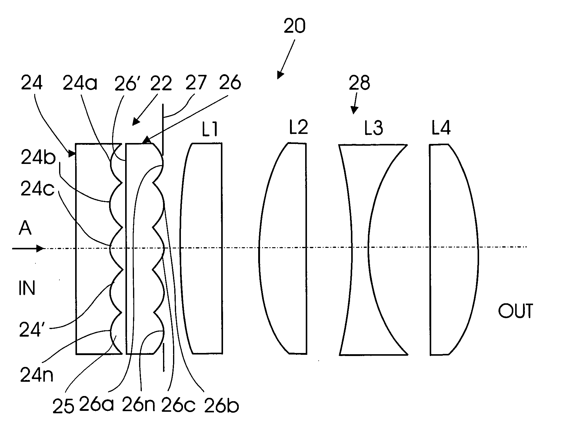
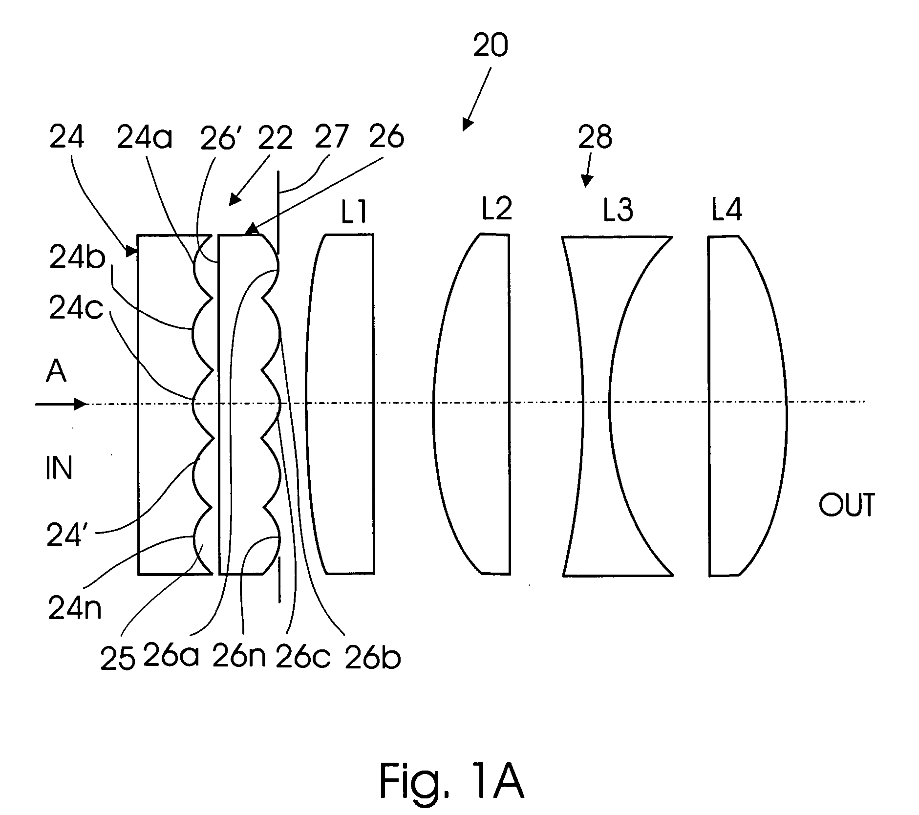
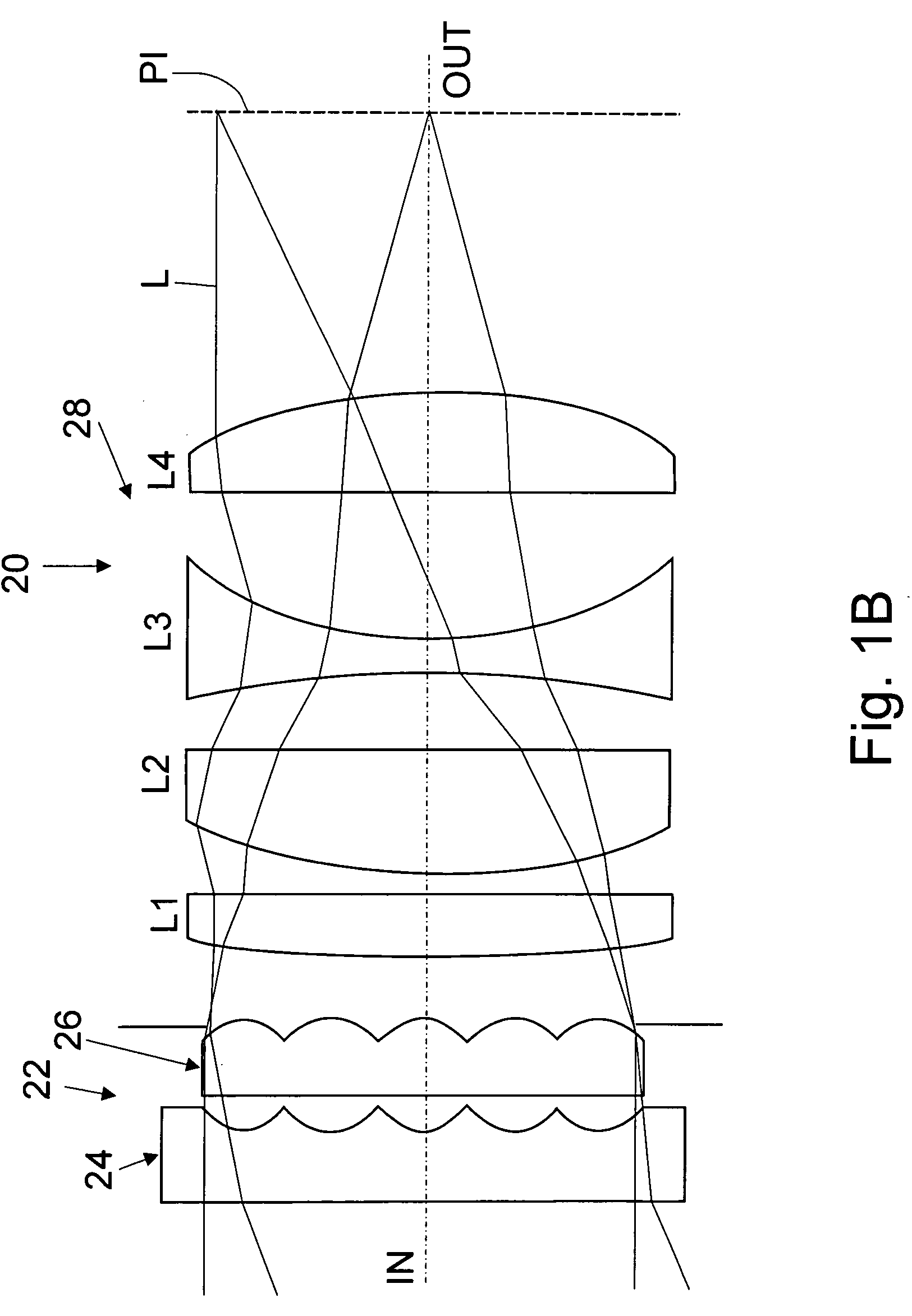
[0031] A general longitudinal sectional view of a wide-angle lens system made in accordance with one embodiment of the invention is shown in FIG. 1A. The optical ray traces for the system of FIG. 1A are shown in FIG. 1B. It can be seen that the system, which in general is designated by reference numeral 20, consists of two main components, one of which is an assembly 22 of at least two microlens arrays 24 and 26 with the same pitch P between the adjacent microlenses 24a, 24b, 24c, . . . . 24n of the array 24 and between the adjacent microlenses 26a, 26b, 26c, . . . . 26n of the array 26. The respective microlenses of both arrays 24 and 26, i.e., microlenses 24a and 26a, 24b and 26b, etc., are axially aligned. The arrangement of microlenses in the microlens array 24, when viewed in the direction of an optical axis indicated by arrow A, is shown in FIGS. 2A and 2B, where FIG. 2A shows hexagonal arrangement and FIG. 2B shows orthogonal arrangement. It is understood that since the micro...


PUM


Abstract

A flat wide-angle lens system of the invention has a reduced axial length and is intended for creating images with extremely wide angle of observation. The system consists of the first component which is intended for reduction of the field angle of light incidence onto the objective and comprises an assembly of at least two microlens arrays with the same pitch between the adjacent microlenses and arranged with respect to each other so as to provide afocality, and a second component that comprises an assembly of conventional spherical or aspherical microlenses that create an image on an image receiver. Each two coaxial microlenses of the microlens arrays of the first component form an inverted microtelescope of Galileo. The outlet aperture of a single microtelescope is made so that spherical aberration can be minimized almost to 0, while field aberrations can be corrected by design parameters of the microlenses.

Description

FIELD OF THE INVENTION [0001] The present invention relates to the field of optics and, more particularly, to a wide-angle flat photographic and projection lens system. More specifically, the invention relates to a wide-angle flat photographic and projection lens system which is built on an entirely new principle of combining a group or groups of flat microlenses with a group or groups of conventional optical lenses. The lens system of the invention may find application in photographic cameras, image projection systems, etc. BACKGROUND OF THE INVENTION [0002] For better understanding the terminology used in the present description and principles of structure of optical systems in general, it would be advantageous to make some short introduction into the field of optical objectives. [0003] An objective is an optical system or a part thereof that faces an object of observation or photographing and that creates a real image of the object turned 180° with respect to the object. Dependin...

Claims


Application Information

Patent Timeline
Patent Type & Authority Applications(United States)
IPC IPC(8): G02B27/10G02B13/04G02B3/00G02B9/00G02B9/60G02B13/06G02B13/18
CPCG02B3/0056G02B13/18G02B13/06G02B3/0068
Inventor GUREVICH, IGORFAYBISHENKO, VICTORVELIKOV, LEONID
Owner MICROALIGN TECH
Why Eureka
Try Eureka