Data transmission device and data transmission method

a data transmission device and data transmission technology, applied in digital transmission, synchronous/start-stop systems, electrical apparatus, etc., can solve the problems of increasing radiation noise, radiation noise, and other electronic devices mounted on the automobile that are not working properly, so as to reduce radiation noise and reduce radiation noise

Inactive Publication Date: 2006-03-09
PANASONIC CORP
View PDF4 Cites 25 Cited by
  • Summary
  • Abstract
  • Description
  • Claims
  • Application Information

AI Technical Summary

Benefits of technology

[0022] Further, even in the case where a twisted pair cable is used for a transmission path, it is possible to reduce the radiation noise due to a common-mode signal caused by an amplitude difference between paired lines.
[0023] Furthermore, by adjusting the phase difference between the reception signal and the transmission signal to 90 degrees or 270 degrees, it becomes possible to comprehensively reduce the radiation noise regardless of the polarity of the common-mode signal.

Problems solved by technology

Incidentally, in the case of a ring-type LAN provided in an automobile, radiation noise may cause malfunctioning of other electronic devices mounted on the automobile.
The common-mode signal causes the occurrence of radiation noise.
Further, in the data transmission apparatus provided with both a reception function and a transmission function, a reception process and a transmission process are carried out by using the same clock so that crosstalk may occur between a reception common-mode signal from a twisted pair cable for receiving data and a transmission common-mode signal from a twisted pair cable for transmitting data, resulting in an increase of radiation noise.
However, in the case of using twisted pair cables to construct a network in an automobile for data transmissions, the effect of radiation noise due to crosstalk cannot be ignored.

Method used


Image

  • Data transmission device and data transmission method
  • Data transmission device and data transmission method
  • Data transmission device and data transmission method

Examples


Embodiment Construction

[0037] A data transmission apparatus of the present embodiment can be used as a data transmission apparatus for constructing a system which employs electrical signals for performing data transmissions via a ring-type network such as MOST (refer to FIG. 10). Further, the data transmission apparatus of the present embodiment can be used as a data transmission apparatus for constructing a system for performing data transmissions using electric signals, where a transmission path for transmission and a transmission path for reception are separate from each other.

[0038] Hereinafter, by taking an example of a data transmission apparatus for constructing a MOST-based data transmission system, a data transmission apparatus and a data transmission method, which are provided by the present invention, will be described.

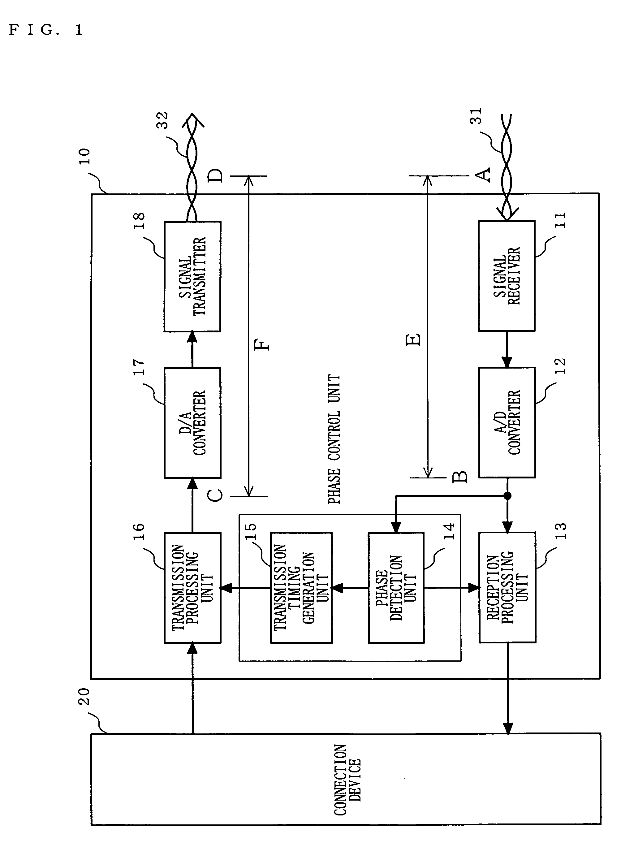
[0039]FIG. 1 is a block diagram illustrating a structure of a data transmission apparatus 10 according to an embodiment of the present invention. The data transmission apparatu...


PUM


Abstract

A signal receiver (11) receives an analog signal via a twisted pair cable (31). An A/D converter (12) converts the analog signal to a digital signal. A phase detection unit (14) detects the phase of the digital signal, and generates a reception timing signal. A transmission timing generation unit (15) controls, based on the reception timing signal, timing for a transmission processing unit (16) to output the digital signal such that the reception signal (point A) and a transmission signal (point D) are different in phase by a predetermined degree. The transmission processing unit (16) outputs, in accordance with the timing, a digital signal obtained by performing mapping on data inputted from a connection device (20). A D/A converter (17) converts the digital signal to an analog signal. A signal transmitter (18) transmits the analog signal via a twisted pair cable (32).

Description

TECHNICAL FIELD [0001] The present invention relates to a data transmission apparatus and a data transmission method, and more particularly, it relates to a data transmission apparatus, which performs telecommunications with another apparatus via different transmission paths for transmission and reception, and a data transmission method executed by the same apparatus. BACKGROUND ART [0002] Recent years have seen intensive studies of networks in which a plurality of devices, such as audio devices, navigation devices, or information terminal devices, are connected to conduct high-speed communications of a large quantity of information, e.g., digitized video and audio data, or computer data, between the devices. Especially in the field of automobiles, in-vehicle networks for performing digital data transmissions have been widely introduced. In the in-vehicle networks, for example, a ring topology is used as a physical topology, and a plurality of nodes are connected together in the rin...

Claims


Application Information

Patent Timeline
Patent Type & Authority Applications(United States)
IPC IPC(8): H04L7/00H04L7/033
CPCH04L7/0334H04L7/00H04L7/033H04L25/49H04L27/00
Inventor KAWADA, HIROTSUGUSAITO, YOSHIYUKISHIBATA, OSAMUSUENAGA, HIROSHISAKAI, TAKAHISAUMEI, TOSHITOMOAKITA, TAKASHIMIZUGUCHI, YUJIKATTA, NOBORU
Owner PANASONIC CORP
Why Eureka
Try Eureka