Time release multisource marker and method of deployment

a multi-source marker and time-release technology, applied in the direction of drilling compositions, chemistry apparatus and processes, constructions, etc., can solve the problems of prohibitively high cost of determining zonal contribution, high cost of production logging tools, and risk of loss of production, so as to delay the release of markers

Inactive Publication Date: 2006-03-09
CORE LAB LP
View PDF66 Cites 120 Cited by
  • Summary
  • Abstract
  • Description
  • Claims
  • Application Information

AI Technical Summary

Benefits of technology

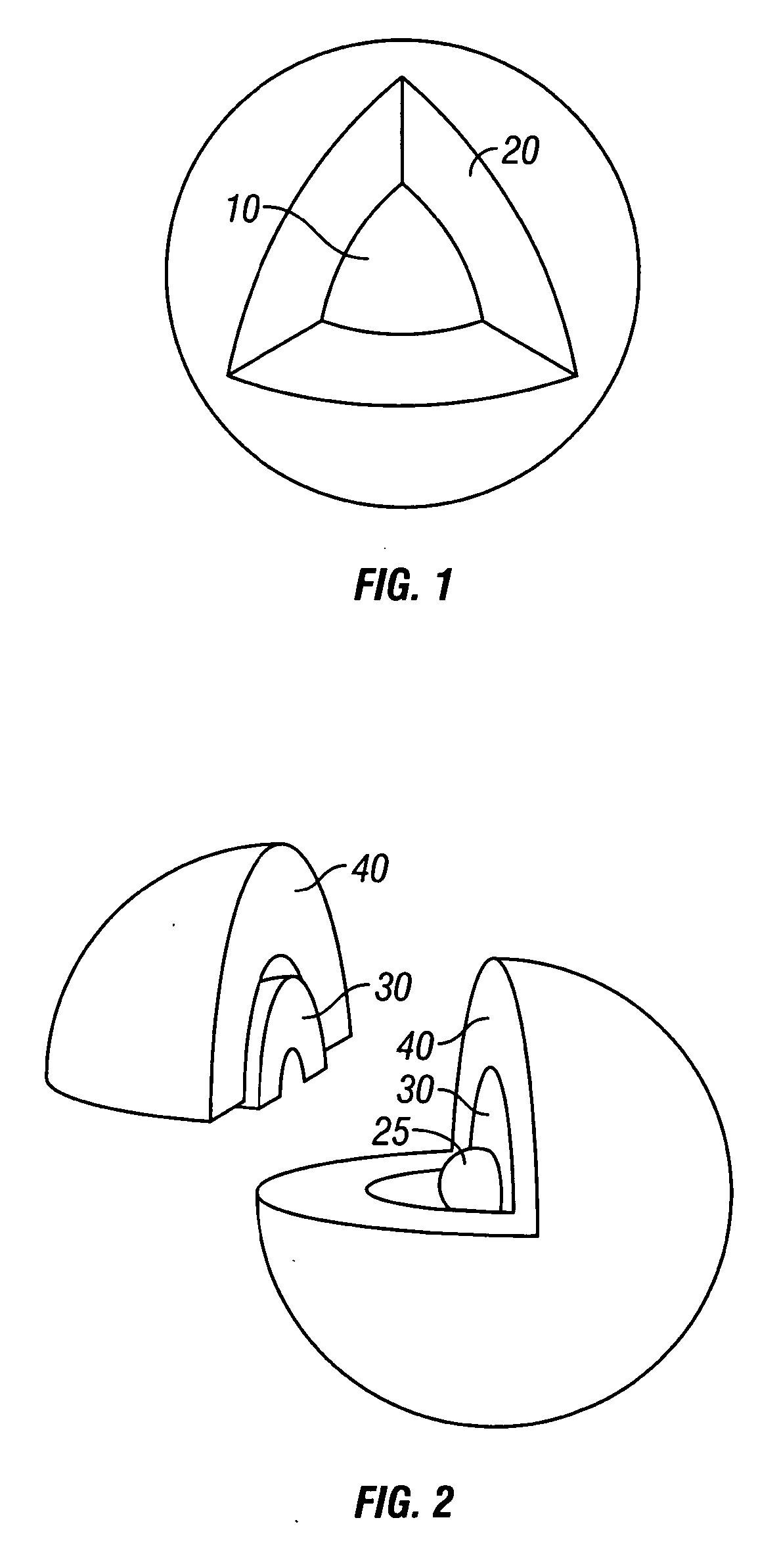
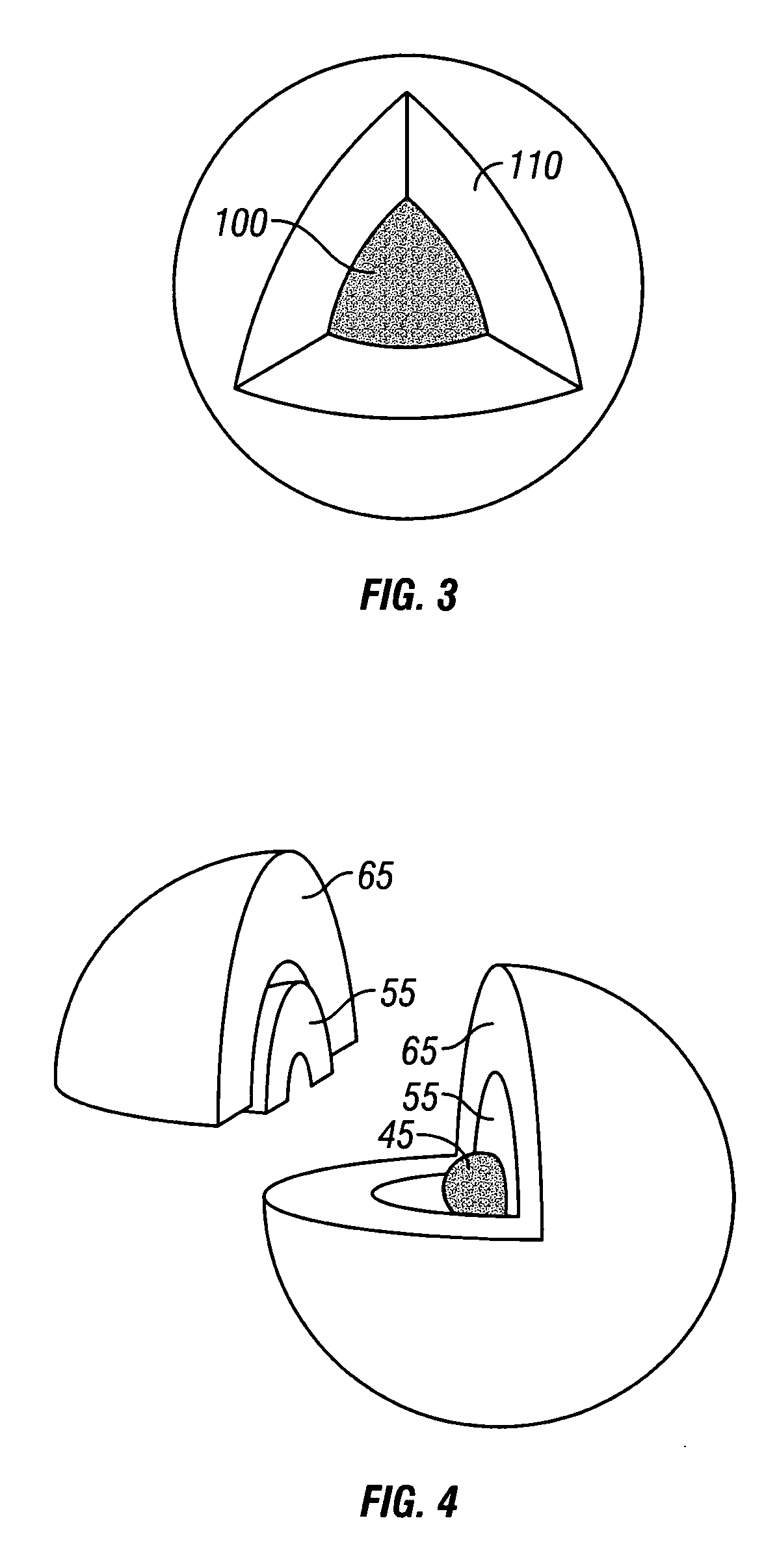
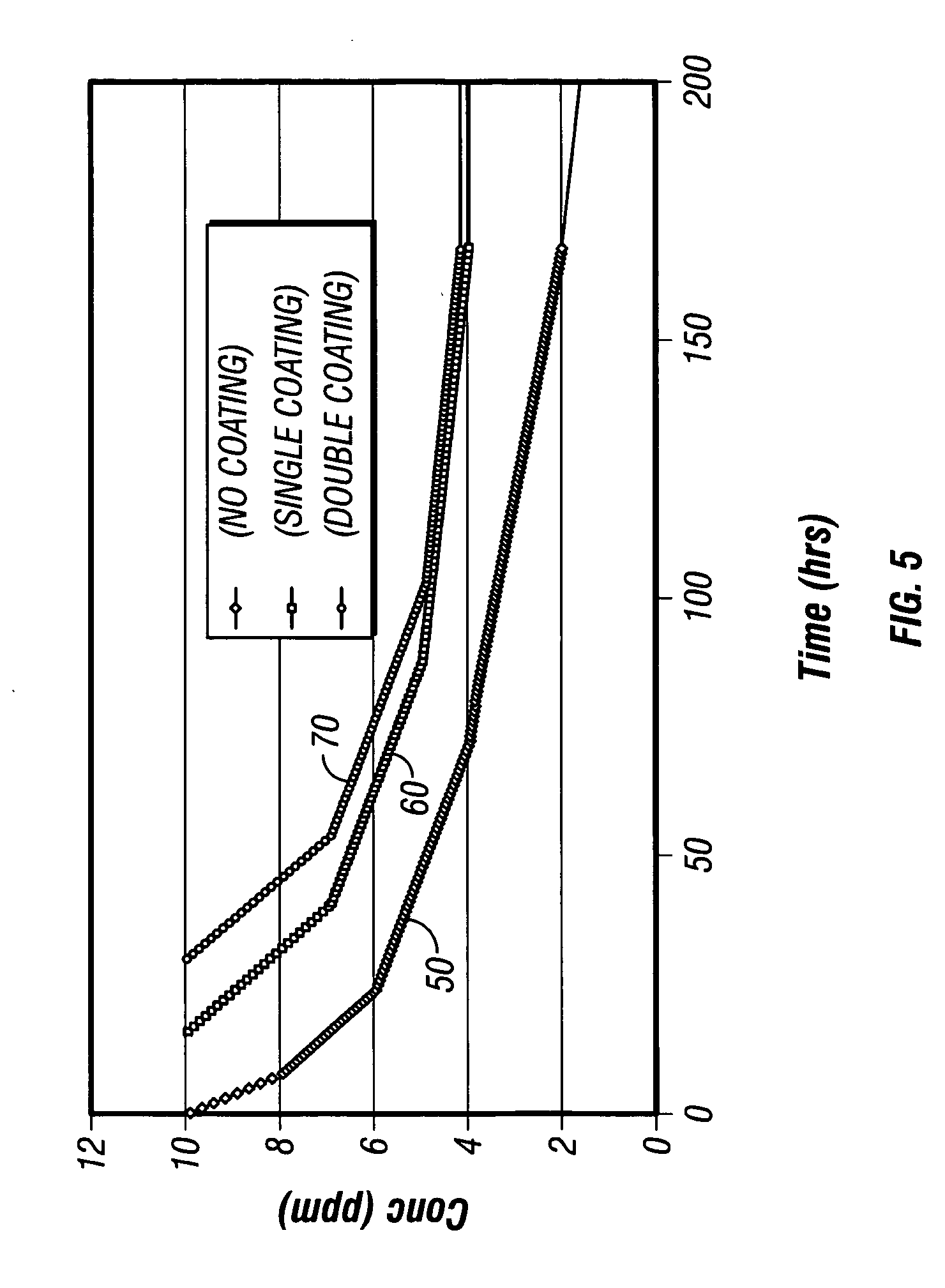
[0015] The present invention provides delayed release markers for use with single reservoir and commingled wells. The invention accomplishes the delayed release of markers by coating or encapsulating the markers with a coating or by coating a proppant which has a marker embedded in it.

Problems solved by technology

Commingling is economically advantageous in many respects but can create the risk of loss of production through differing zonal pressure regimes.
In the prior art, the cost of determining zonal contribution can be prohibitively expensive.
Production logging tools are expensive and require expertise to operate and maintain.
The use of the tools is also time consuming and introduces potential problems such as broken, lost, or stuck tools and wellbore damage.
However, due to dispersion, wash out, and other phenomena, markers placed in zones decrease in concentration rapidly after injection.
The prior art provides several examples of marking various recovery fluids and proppant in order to determine zonal contribution, but does not provide a method for delaying the release, in time or rate, of a marker.
However, the breaker is not used for tracing purposes, is combined with proppant or a marker, and is not used to determine the extent of fracturing.
However, the encapsulated chemical is not used for tracing purposes, is not combined with proppant, and is not used in relation to well fracturing.

Method used


Image

  • Time release multisource marker and method of deployment
  • Time release multisource marker and method of deployment
  • Time release multisource marker and method of deployment

Examples


example 1

[0044] 200 mg dry, solid particles of 2,4,5 trifluorobenzoic acid or flourobenzoate salt are sorted for particle size by mesh screens of sizes 20 to 40. These particles are fluidized in a UniGlatt fluidized bed apparatus using a Wurster column. These particles are then sprayed with a liquid cellulose acetate consisting of about 40% percent solids. A spray nozzle with level setting and air pressure of 2.7 bars combined with an exhaust filter bumping scheme of 10 seconds duration with a 2 minute interval is employed in the coating operation. The inlet temperature is 50 degrees Celsius and the feed rate about 15 milliliters (ml) per minute. The spray time is about 30 minutes. The capsules have a coating thickness which varies from 5 to 65 microns and an average coating thickness of 40 microns.

example 2

[0045] A 5% solution of 2,4,5 triflourobenzoic acid in distilled water is prepared at room temperature. The 5% 2,4,5 triflourobenzoic acid or flourobenzoate salt solution is then added to ceramic beads having a mesh size of 20 / 40 to create a slurry. In this example, the batch size is 10 kg.

[0046] The slurry is stirred for 15 minutes using a paddle stirrer to saturate the ceramic beads with the 2,4,5 triflourobenzoic acid or flourobenzoate salt. The stirred slurry is dried in a convection oven at approximately 38° C. for 30 minutes until the slurry contains about 0.25% moisture. The marker concentration is increased from 5% to 10% by successive addition of the 5% marker solution to the dried slurry. Once the 5% marker solution has been added to the dried slurry, the slurry is again heated to obtain between about 0.1%-8% moisture.

[0047] The coatings are prepared by first combining an epoxy resin and catalyst according to the manufacturer's specifications. The catalyzed epoxy is adde...

example 3

[0049] A 5% solution of 2,4,5 triflourobenzoic acid in distilled water is prepared at room temperature. The 5% 2,4,5 triflourobenzoic acid or flourobenzoate salt solution is then added to ceramic beads having a mesh size of 20 / 40 to create a slurry. In this example, the batch size is 10 kg.

[0050] The slurry is stirred for 15 minutes using a paddle stirrer to saturate the ceramic beads with the 2,4,5 triflourobenzoic acid or flourobenzoate salt. The stirred slurry is dried in a convection oven at approximately 38° C. for 30 minutes until the slurry contains about 0.25% moisture. The marker concentration is increased from 5% to 10% by successive addition of the 5% marker solution to the dried slurry. Once the 5% marker solution has been added to the dried slurry, the slurry is again heated to obtain between about 0.1%-8% moisture.

[0051] An epoxy coating and hardener are combined and mixed and added to the dried slurry. The catalyzed epoxy is added to the saturated proppant at a rati...


PUM

PropertyMeasurementUnit
thicknessaaaaaaaaaa
time delayaaaaaaaaaa

Abstract

The present invention provides time released markers for use with single reservoir and commingled wells. The invention accomplishes the time release of markers by coating or encapsulating marker particles or by coating a proppant which has been saturated with a marker. After coating or encapsulation, the marker is injected into a well as is known in the art. The marker remains in the well. The marker is released after an elapsed of time. The elapsed time can be in a wide range. After the elapsed time, production is taken from the well and tested for the presence of the marker. Various types of known analyses can be performed to test for the presence and concentration of the marker in the production fluid. The concentration of the marker in the production fluid allows the apportioning of production from the reservoir. In addition, different markers may be added to each zone within a reservoir where each marker has a different elapsed time increment. The zones can be any different layer or area in the reservoir such as different strata or layer of rock, limestone or sand. Differing marker combinations allow contribution from different zones to be monitored over an extended time.

Description

FIELD OF THE INVENTION [0001] The present invention relates to chemically marking a reservoir in an oil and gas well and more particularly, to a method for marking a reservoir during the fracturing, gravel packing or acidizing phase of well completion and still more particularly, to a method for using a marker combined with proppant to chemically mark a reservoir wherein the marker may be released from its association with the proppant at a delayed time and release rate. BACKGROUND OF THE INVENTION [0002] In order to increase the economics of oil well productions, many wells in the United States today use hydraulic fracturing to draw hydrocarbons through subterranean formations called reservoirs. Fracturing is a method of stimulating production by opening new flow channels in the reservoir surrounding a production well. During fracturing, high viscosity fracturing fluid is pumped into a reservoir under pressure high enough to cause the reservoir to crack open, forming passages throu...

Claims


Application Information

Patent Timeline
Patent Type & Authority Applications(United States)
IPC IPC(8): C09K8/02C09K8/03
CPCE21B47/1015C09K8/03E21B47/11
Inventor ANDERSON, DAVID KINGFERGUSON, ROYCE BECK
Owner CORE LAB LP
Why Eureka
Try Eureka