Gas fuel feed device

a fuel feed device and fuel injection technology, applied in the direction of valve operating means/releasing devices, machines/engines, transportation and packaging, etc., can solve the problems of inability to cope with an engine with a wide power range, excessive fuel injection quantity at the time of idle, and inability to control idle speed, etc., to achieve a controllable range of fuel injection quantity control

Inactive Publication Date: 2006-03-16
ISUZU MOTORS LTD
View PDF2 Cites 9 Cited by
  • Summary
  • Abstract
  • Description
  • Claims
  • Application Information

AI Technical Summary

Benefits of technology

[0015] It is an object of this invention to solve the problem above-mentioned, and to enlarge a controllable range of the fuel injection quantity control by the injector in a gas fuel supply system.

Problems solved by technology

However, there has been a problem that, if the injector source pressure is always constant, a controllable range of the increase and decrease control of the fuel injection quantity becomes narrow and thus it becomes impossible to cope with an engine having a wide power range, since the minimum injection quantity and the maximum injection quantity of the fuel is determined by the performance of the injector 64.
If such an injector is adopted that has a superior controllability in a high power region where the fuel injection quantity is large, the fuel injection quantity at the time of idling may become excessive and an idling speed may not be controlled.
In particular, the maximum fuel injection quantity of the fuel depends on the injector source pressure, and thus is limited if a control by the injector only is performed.

Method used


Image

  • Gas fuel feed device
  • Gas fuel feed device
  • Gas fuel feed device

Examples


Embodiment Construction

[0028] One preferable embodiment of this invention will now be described in detail with reference to accompanying drawings.

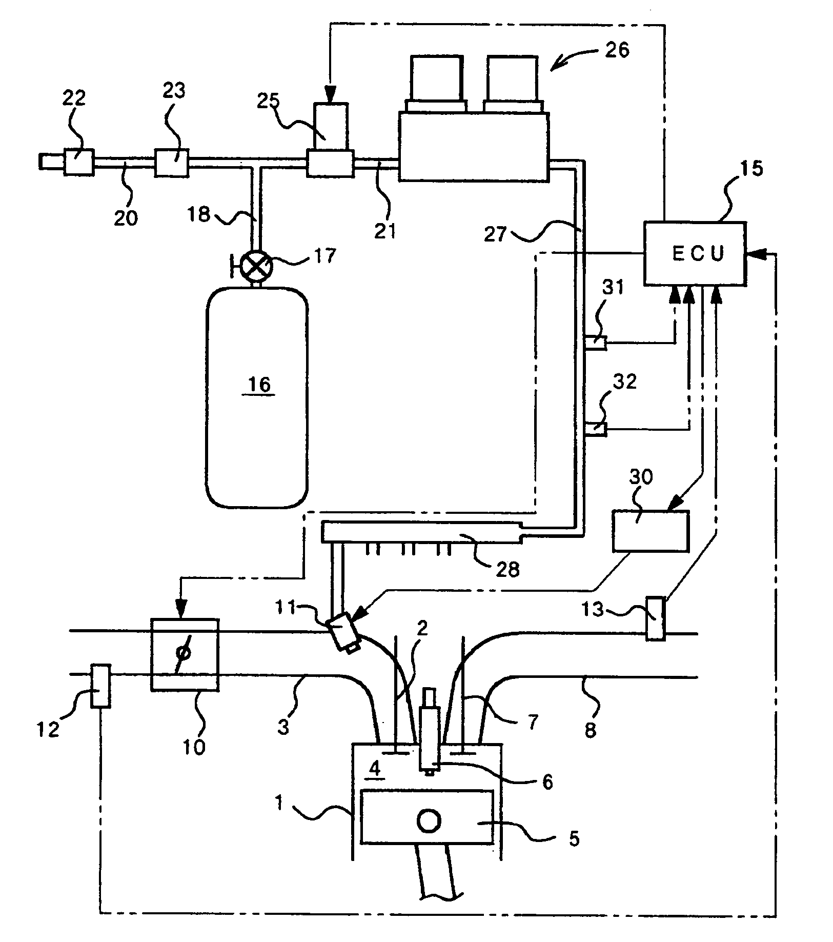
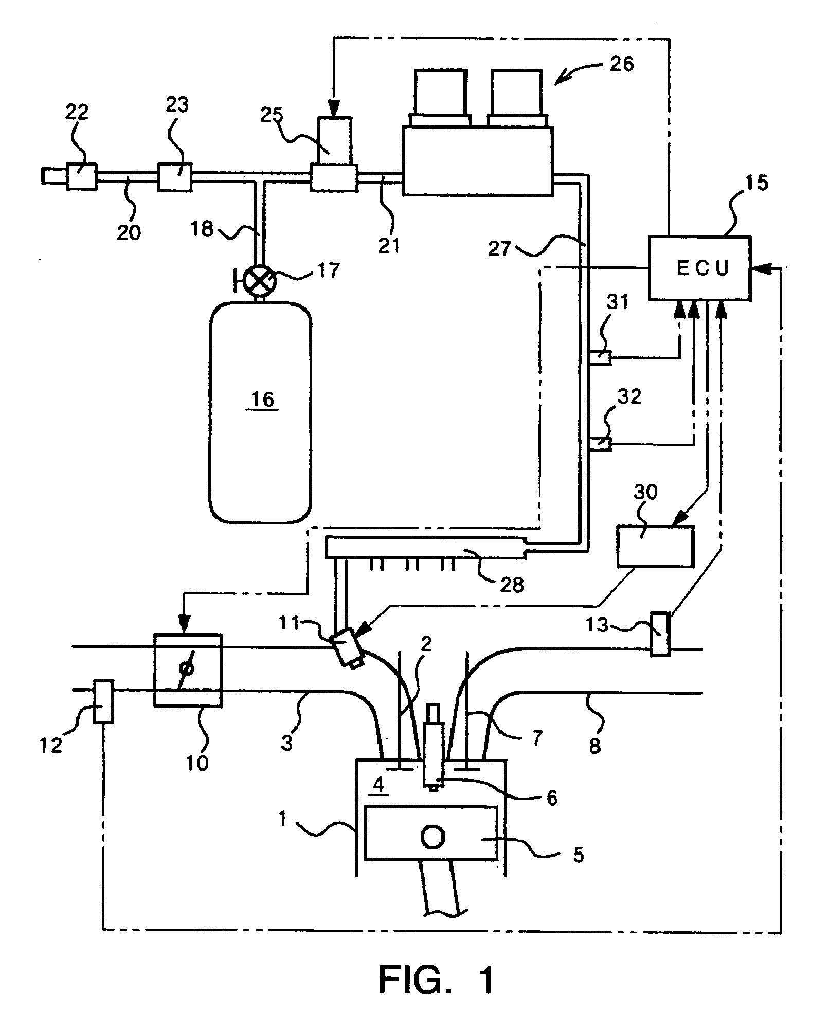
[0029] Initially, a gas fuel supply system as a whole of this embodiment will generally be described with reference to FIG. 1.

[0030] In a gas fuel powered internal combustion engine (simply referred to as an engine hereinafter) of this embodiment, intake air (fuel-air mixture) is sucked into a combustion chamber 4 from an intake pipe 3 when an intake valve 2 of each cylinder 1 is opened. The intake air is then compressed by a piston 5, and ignited by a spark plug 6 to burn. When an exhaust valve 7 is opened, exhaust gas is discharged to an exhaust pipe 8. These processes are repeated continuously.

[0031] The intake pipe 3 is provided with a throttle valve 10 and an injector 11. The throttle valve 10 is interlocked with the accelerator opening degree of the vehicle and opens and closes the intake pipe 3 to adjust the amount of the intake air. The injector 11 is...


PUM


Abstract

It is an object of this invention to provide a gas fuel supply system in which a controllable range in the fuel injection quantity control by an injector is enlarged. According to one preferable aspect of this invention, the gas fuel supply system comprises an injector provided in an intake pipe of an internal combustion engine, a fuel supply passage for supplying the gas fuel to the injector, and means for controlling pressure of the gas fuel supplied to the injector through the fuel supply passage by using negative pressure in the intake pipe such that the pressure of the gas fuel increases if the negative pressure in the intake pipe decreases, and the pressure of the gas fuel decreases if the negative pressure in the intake pipe increases.

Description

TECHNICAL FIELD [0001] This invention relates to a gas fuel supply system for supplying gas fuel to an internal combustion engine in which the gas fuel such as compressed natural gas burns. BACKGROUND ART [0002] In recent years, gas fuel such as natural gas is adopted as one of the alternative fuels to gasoline or light oil. In case that the gas fuel is applied for the internal combustion engine of a vehicle, as disclosed in JP 2000-337208A, such a gas fuel supply system is known for example that a high-pressure cylinder (fuel tank) filled up with the compressed natural gas is mounted on the vehicle, and the gas fuel supplied from the high-pressure cylinder is decompressed with a regulator and then injected into an intake pipe of the internal combustion engine by an injector. [0003] A conventional gas fuel supply system will now be described with reference to FIG. 6. [0004] As shown in the figure, a regulator 61 for decompressing and regulating the pressure of the gas fuel is connec...

Claims


Application Information

Patent Timeline
Patent Type & Authority Applications(United States)
IPC IPC(8): F02M21/02F02B43/00
CPCF02B43/00Y02T10/32F02D19/027F02D19/022F02M21/0239Y10T137/7797Y10T137/7795Y02T10/30
Inventor TOKUNAGA, MOTOHISA
Owner ISUZU MOTORS LTD
Why Eureka
Try Eureka