Logging tool with a parasitic radiation shield and method of logging with such a tool

Active Publication Date: 2006-03-16
SCHLUMBERGER TECH CORP
View PDF6 Cites 24 Cited by
  • Summary
  • Abstract
  • Description
  • Claims
  • Application Information

AI Technical Summary

Benefits of technology

[0007] In a preferred embodiment, the tool further comprises a stabilizer located at the periphery around the outer collar surface, wherein this stabilizer comprises a stabilizer wall defined by an inner stabilizer surface and an outer stabilizer surface, and wherein the radiation shield is located between this inner collar surface and this outer stabilizer surface. The stabilizer enhances the contact between the tool and the formation by reducing the space available for mud between the tool and the formation.
[0009] In a preferred embodiment, the radiation shield is located between the emitting radiation source and the radiation detector and has a length along the axis, which is less than 80% of the distance between the source and the detector. The radiation shield has a thickness in the cross section perpendicular to the major axis, which is preferably less than 40% of the width of the tool at the position of the radiation source. This makes it possible to eliminate a significant fraction of the radiation that are coming from source and that have not passed through the borehole fluid and the formation, but whose path was entirely inside the collar and the stabilizer.
[0012] In a preferred embodiment, this invention is directed toward a gamma-ray logging-while-drilling density tool. The system comprises a source of gamma radiation and one or more gamma ray detectors. Multiple detectors (2 or more) provide better efficiency and allow compensation for the effect of mud and mudcake intervening between the tool and the formation It is clear, however, that the basic concepts of the invention could be employed in other types and classes of logging, logging-while-drilling or measurement-while-drilling systems. As an example, the invention can be used in a neutron porosity system for measuring formation porosity, wherein the sensor comprises a neutron source and one or more neutron detectors.

Problems solved by technology

Downhole measurements of formation density are of the scattering type since it is not usually possible to insert the formation material directly between source and detector, with the possible exception of rock samples removed from the formation.
Furthermore, particulates from the drilling fluid tend to buildup on the borehole wall.
This buildup is commonly referred to as mudcake, and adversely affects the response of the system.
In this way, intervening material between the tool and the borehole wall will adversely affect the tool response.
Intervening material in the tool itself between the active elements of the tool and the outer radial surface of the tool will again adversely affect the tool response by producing a background of scattered radiation which is independent of the presence of the borehole fluid, the mudcake or the formation.
This tends to minimize intervening material within the tool, and positions source and detectors near the borehole environs, but often at the expense of decreasing the efficiency of shielding and collimation.
Those apparatus, because they use a framework totally made of high-density materials, are heavy and brittle, and in harsh drilling conditions, can be broken resulting in the destruction and possibly the loss of the instrument package and more critically the loss of the radioactive source.
The problem of providing shielding in the collar and 10 the stabilizer has not been yet addressed successfully.

Method used


Image

  • Logging tool with a parasitic radiation shield and method of logging with such a tool
  • Logging tool with a parasitic radiation shield and method of logging with such a tool
  • Logging tool with a parasitic radiation shield and method of logging with such a tool

Examples


first embodiment

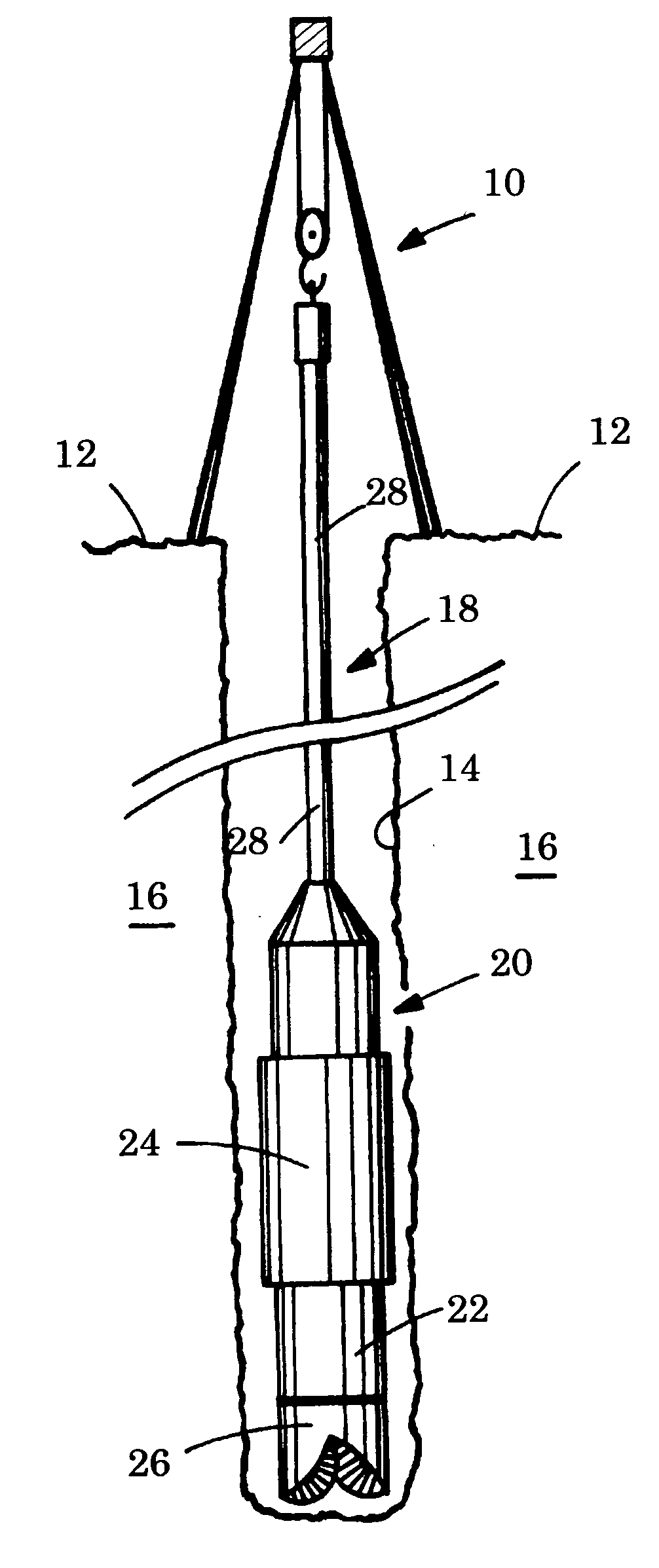
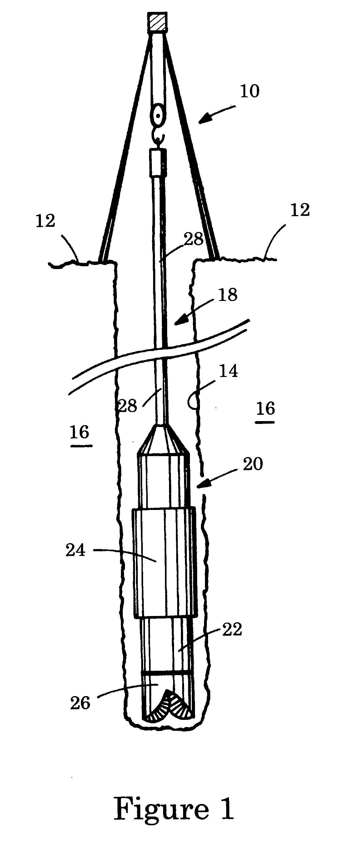
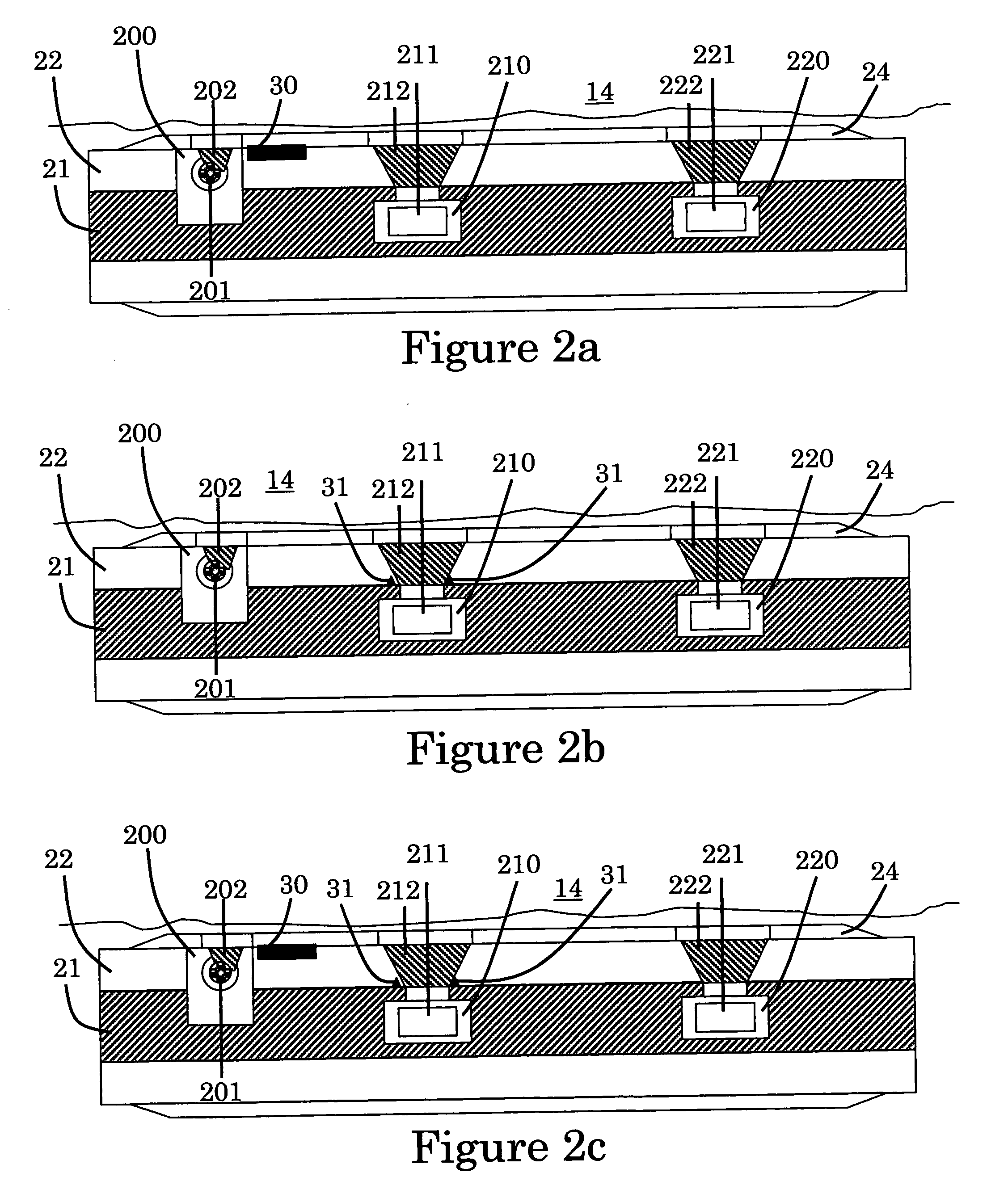
[0022]FIGS. 2a, 2b and 2c illustrate conceptually radiation shields on the tool 20 of FIG. 1 shown in side view on the major axis of the tool. In a first embodiment, the tool is a logging-while-drilling gamma-ray scattering tool with a chemical radioactive source. The tool 20 is made of an elongated tool body 21 and a drill collar 22 disposed peripherally around the tool body 21. In the illustrated tool, a stabilizer 24 is disposed peripherally around the drill collar 22; the stabilizer is optional and reduces the amount of mud between the tool and the formation wall and therefore the influence of the borehole fluid on the measurement. The tool 20 receives one source collimation window 202 through which the earth formation 16 is illuminated by the radiation emitted from the radioactive source, and two detector collimation windows 212 and 222 through which the radiation coming from the outside of the tool 20 is detected. In the illustrated tool, a source of gamma radiation 201 illumi...

second embodiment

[0035] In a second embodiment, the tool 20 is a logging-while-drilling density tool with an electronic radiation source. The source 201 is an x-rays generator. The shielding materials need to be inserted into the structural materials of the tool body, collar or stabilizer with the intent to optimize shielding with a minimal impact on the structural strength of the tool. Shielding 5 materials for lower energy gamma-rays or x-rays could be lighter materials.

third embodiment

[0036] In a third embodiment, the tool 20 is a logging-while-drilling neutron scattering tool with a chemical or electronic neutron source. The source 201 is a chemical source, as Radium-Beryllium source or an electronic source like pulsed neutron generator. The shielding materials need to be inserted into the structural materials of the tool body, collar or stabilizer with the 10 intent to optimize shielding with a minimal impact on the structural strength of the tool. Shielding materials for neutrons will typically be hydrogenous materials and / or neutron absorbing materials, like boron or cadmium for slow neutrons; and will typically be high atomic number materials like tungsten and / or hydrogenous materials for fast neutrons.


PUM


Abstract

It is described a logging tool 20 for underground formations surrounding a borehole 14, comprising an elongated body 21 along a major axis; a collar 22 disposed peripherally around said body 21 having a collar wall defined by an inner and an outer surface; a radiation emitting source 201 arranged to illuminate the earth formation 16 surrounding the borehole; at least one radiation detector 211 arranged to detect radiation reflected by the earth formation resulting from illumination by the source 201; at least one source collimation—window 202 and one detector collimation window 212 through which the earth formation is illuminated and radiation is detected; and characterized in that it further comprises at least one radiation shield 30 located between said inner collar surface and the outer surface of the tool, said radiation shield positioned so as to eliminate parasitic radiation that has not traversed the outer collar.

Description

FIELD OF THE INVENTION [0001] This invention relates to logging of oil, water or gas well in underground formations surrounding a borehole and more particularly to a logging tool with a parasitic radiation shield such as a logging-while-drilling gamma ray density measurement tool. DESCRIPTION OF THE PRIOR ART [0002] In hydrocarbon exploration and production, it is of prime importance to determine if a given earth formation contains hydrocarbon, and the amount of hydrocarbon within the formation. Therefore, formation properties while drilling or in a freshly drilled hole are measured to predict the presence of oil, gas and water in the formation. These formation properties may be logged with wireline tools, logging while drilling (LWD) tools, or measurement while drilling (MWD) tools. One method to predict formation properties is to measure the density of material in earth formation using a source of nuclear radiation and a radiation detector. The density of a material can be determi...

Claims


Application Information

Patent Timeline
IPC IPC(8): G01V5/12G01V3/24
CPCG01V5/125G01V5/107
Inventor LABOUS, LAURENTSTOLLER, CHRISTIAN
Owner SCHLUMBERGER TECH CORP
Why Eureka
Try Eureka