
Thermal electromagnetic radiation detector comprising an absorbent membrane fixed in suspension

Inactive Publication Date: 2006-03-16
COMMISSARIAT A LENERGIE ATOMIQUE ET AUX ENERGIES ALTERNATIVES +1
View PDF39 Cites 24 Cited by
  • Summary
  • Abstract
  • Description
  • Claims
  • Application Information

AI Technical Summary

Benefits of technology

[0007] The object of the invention is to remedy these drawbacks and more particularly to provide a detector having a high ratio of the surface of the bolometer sensitive to radiation over the total surface of the bolometer, while simplifying the manufacturing process thereof.

Problems solved by technology

This results in a complex manufacturing process requiring a large number of manufacturing steps and thus presenting high production costs.
In particular, the presence of the electric interconnecting part in contact with the absorption stage can have a detrimental effect on the absorption quality and on the sensitivity of the detector.
In addition, fabricating an absorption stage having a good flatness is made difficult by the presence of the interconnecting part.

Method used


Image

  • Thermal electromagnetic radiation detector comprising an absorbent membrane fixed in suspension
  • Thermal electromagnetic radiation detector comprising an absorbent membrane fixed in suspension
  • Thermal electromagnetic radiation detector comprising an absorbent membrane fixed in suspension

Examples


Embodiment Construction

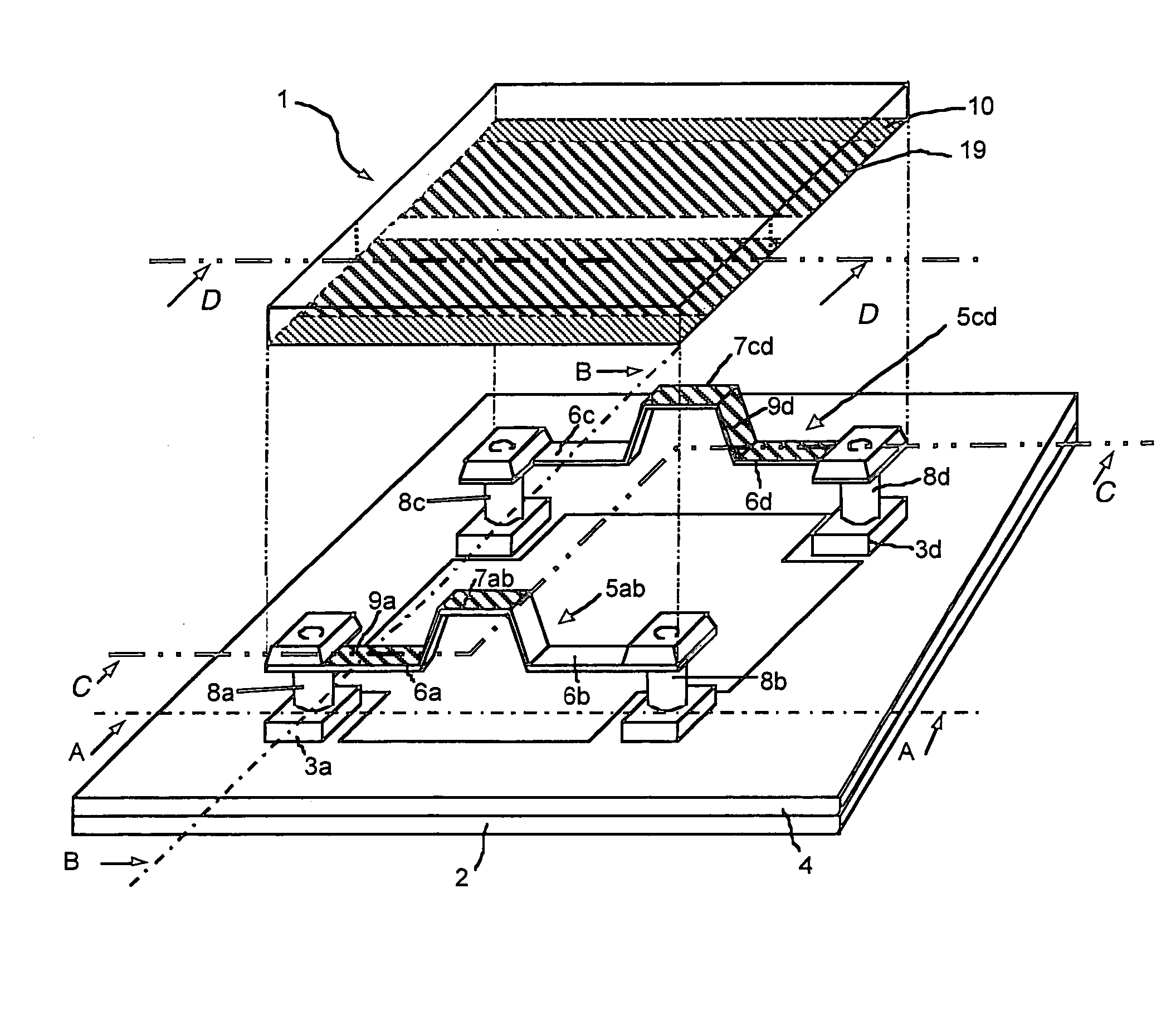
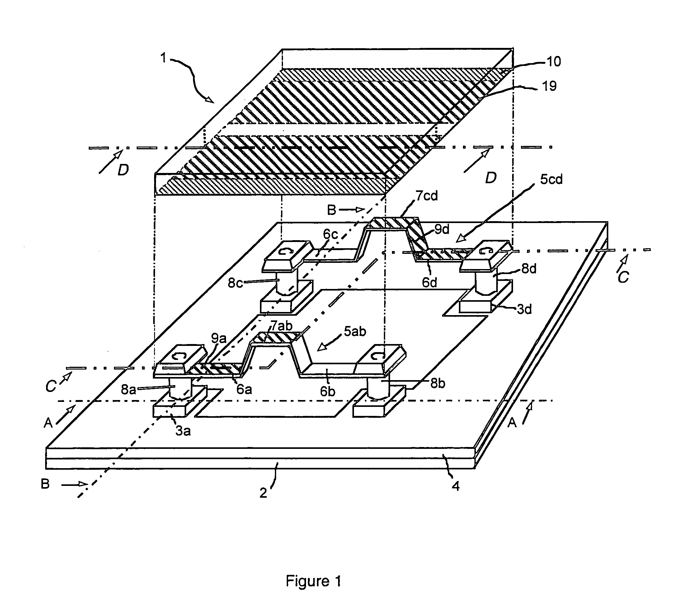
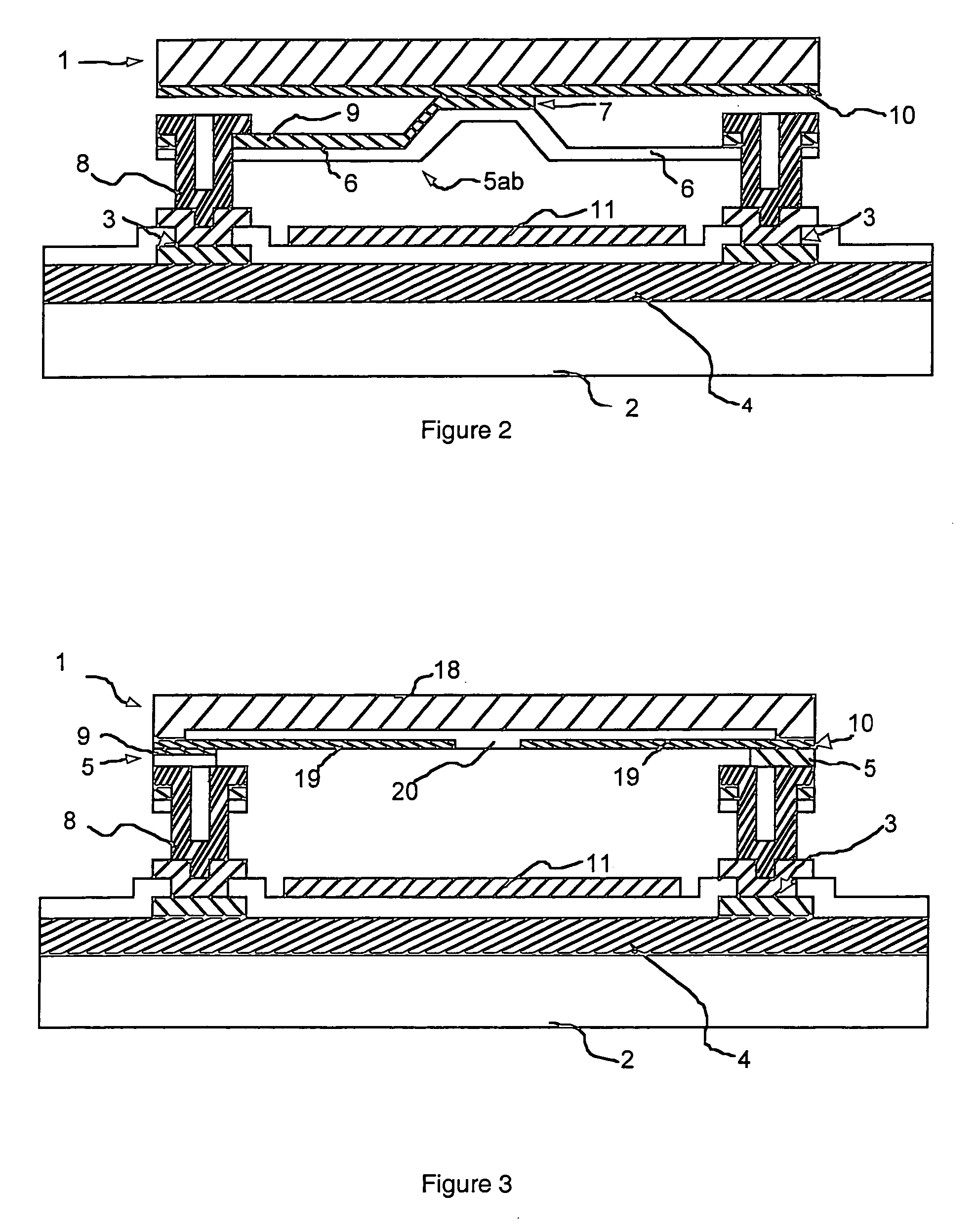
[0033] In FIG. 1, a thermal electromagnetic radiation detector comprises an absorbent membrane 1 fixed in suspension by two thermally insulating support parts 5 onto a front face of a substrate 2. The membrane comprises for example a layer made of a material having a resistivity varying according to the temperature, for example amorphous silicon. The substrate 2 comprises two electric connection terminals 3a and 3d electrically connected to the membrane 1, as described below. The substrate 2 can comprise an integrated circuit 4 connected to the connection terminals 3, enabling the detector to be biased and the output electric signal of the detector to be processed. When related to infrared radiation, the detector extends over a square field whose side is from ten to a hundred micrometers. The substrate 2 is preferably flat and can be made of silicon.

[0034] In FIG. 1, the two support ends 5, arranged between the substrate 2 and membrane 1, are each formed by a bridge (5ab and 5cd) h...


PUM


Abstract

The absorbent membrane of the detector is fixed in suspension by at least one thermally insulating support part onto a front face of a substrate comprising at least two electric connection terminals electrically connected to the membrane, for example by means of conducting layers. The support part has at least one base end and a raised zone. The base end is fixed to a top part of a conducting pillar having a base fixedly secured to one of the electric connection terminals. A substantially flat zone of a bottom face of the membrane is directly in contact with the raised zone of the support part. The support part is preferably formed by a bridge having a second base end fixed to a top part of a second pillar, the raised zone being formed by a flat middle part of the bridge.

Description

BACKGROUND OF THE INVENTION [0001] The invention relates to a thermal electromagnetic radiation detector comprising an absorbent membrane fixed in suspension by thermally insulating support means onto a front face of a substrate comprising at least two electric connection terminals electrically connected to the membrane, the support means comprising at least one support part arranged between the substrate and membrane and having at least one base end and a raised zone. [0002] 1. State of the Art [0003] Recent technological progress in silicon microelectronics and achievement of thin films has given a new boost to the technology of thermal radiation detectors comprising an absorbent membrane fixed in suspension on a substrate by thermally insulating support means. [0004] Microelectronics is based on collective processes performed at silicon wafer level, processes which thermal detector technologies can also benefit from in many respects. These collective techniques in fact provide th...

Claims


Application Information

Patent Timeline
IPC IPC(8): H01L27/14G01J5/10G01J5/20
CPCG01J5/02G01J5/20G01J5/10G01J5/023
Inventor YON, JEAN-JACQUESASTIER, ASTRIDVILAIN, MICHEL
Owner COMMISSARIAT A LENERGIE ATOMIQUE ET AUX ENERGIES ALTERNATIVES
Learn More