White, single or multi-color light emitting diodes by recycling guided modes

a light-emitting diode and guided mode technology, applied in the field of light-emitting diodes, can solve the problems of affecting the efficiency of the led, and affecting the color balance of the led,

Inactive Publication Date: 2006-03-16
RGT UNIV OF CALIFORNIA
View PDF16 Cites 116 Cited by
  • Summary
  • Abstract
  • Description
  • Claims
  • Application Information

AI Technical Summary

Benefits of technology

[0022] The present invention discloses a white, single or multi-color light emitting diode (LED) comprising a mirror for reflecting photons within the LED; a first active region, adjacent the mirror, comprised of one or more current-injected layers for emitting photons when electrically biased in a forward direction; a second active region, adjacent the first active region, comprised of one or more optically-pumped layers for emitting photons, wherein the optically-pumped layers are optically excited by the photons emitted by the current-injected layers, thereby recycling guided modes; and an output interface, adjacent the second active region, for allowing the photons emitted by the optically-pumped layers to escape the LED as emitted light.

Problems solved by technology

Unfortunately, most of the light emitted within an LED is lost due to internal reflections at the semiconductor-air interface.
This higher extraction efficiency is, however, limited to values in the 40% range as the micro-cavity structure also leads to very efficient emission into guided modes.
However, this solution is costly and the overall light output of each RGB LED degrades at a different rate, thereby resulting in an eventual color imbalance.
The problems with the structure of FIGS. 3A and 3B are the poor efficiencies of the LED, the optical coupling between the LED and phosphor, the low brightness, and the non-planar fabrication technique.
The PRS-LED can also be designed to emit other colors by the proper combination of emitting species, which is not possible with conventional LEDs.
The drawbacks here are the mediocre optical coupling efficiency between emitters and the poor efficiency of the active blue LED.

Method used


Image

  • White, single or multi-color light emitting diodes by recycling guided modes
  • White, single or multi-color light emitting diodes by recycling guided modes
  • White, single or multi-color light emitting diodes by recycling guided modes

Examples


Embodiment Construction

[0045] In the following description of the preferred embodiment, reference is made to the accompanying drawings which form a part hereof, and in which is shown by way of illustration a specific embodiment in which the invention may be practiced. It is to be understood that other embodiments may be utilized and structural changes may be made without departing from the scope of the present invention.

[0046] Overview

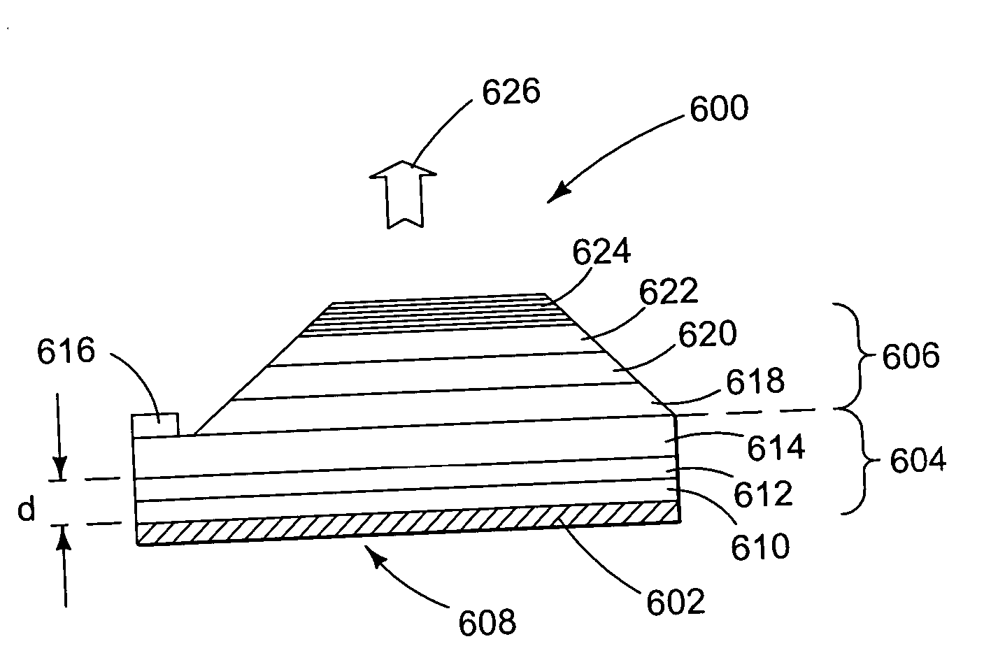
[0047] The present invention describes new LED structures that provide white, single or multi-color light and increased light extraction efficiency while retaining a planar structure. The new LED structures have direct emission outside the structure and, in addition, convert guided light in different colors through absorption and re-emission by additional emitting species, to achieve a high-efficiency white, single or multi-color LED.

[0048] The structure includes a bottom mirror, one or more current-injected layers, one or more electrically-passive, optically-pumped layer...


PUM


Abstract

A white, single or multi-color light emitting diode (LED) includes a mirror for reflecting photons within the LED; a first active region, adjacent the mirror, including one or more current-injected layers for emitting photons when electrically biased in a forward direction; a second active region, adjacent the first active region, including one or more optically-pumped layers for emitting photons, wherein the optically-pumped layers are optically excited by the photons emitted by the current-injected layers, thereby recycling guided modes; and an output interface, adjacent the second active region, for allowing the photons emitted by the optically-pumped layers to escape the LED as emitted light.

Description

BACKGROUND OF THE INVENTION [0001] 1. Field of the Invention [0002] The invention is related to light emitting diodes (LEDs), and more particularly, to new structures for producing white, single or multi-color LEDs with high extraction efficiency by recycling guided modes. [0003] 2. Description of the Related Art [0004] (Note: This application references a number of different publications and patents as indicated throughout the specification by one or more reference numbers within brackets, e.g., [x]. A list of these different publications and patents ordered according to these reference numbers can be found below in the section entitled “References.” Each of these publications and patents is incorporated by reference herein.) [0005] A light emitting diode (LED) is a semiconductor device that emits light when electrically biased in the forward direction. This effect is a form of electroluminescence. [0006] LEDs are typically comprised of a chip of semiconducting material impregnated...

Claims


Application Information

Patent Timeline
Patent Type & Authority Applications(United States)
IPC IPC(8): H01L21/00H01L33/00H01L33/10H01L33/20H01L33/22H01L33/32H01L33/40H01L33/50
CPCH01L33/08H01L33/10H01L33/20H01L33/505H01L33/32H01L33/405H01L33/22
Inventor SCHWACH, CAROLEWEISBUCH, CLAUDE CHARLES AIMEDENBAARS, STEVEN P.BENISTY, HENRINAKAMURA, SHUJI
Owner RGT UNIV OF CALIFORNIA
Why Eureka
Try Eureka