Motor drive apparatus, vehicle having the same mounted therein, and computer readable storage medium having a program stored therein to cause computer to control voltage conversion

a technology of motor drive and computer, which is applied in the direction of motor/generator/converter stopper, process and machine control, etc., can solve the problems of increasing switching noise and switching loss, increasing the frequency and increasing the number of npn transistors generating noise, and increasing the number of transistors generating noise, so as to reduce switching noise and reduce switching loss.

Active Publication Date: 2006-03-16
TOYOTA JIDOSHA KK
View PDF4 Cites 43 Cited by
  • Summary
  • Abstract
  • Description
  • Claims
  • Application Information

AI Technical Summary

Benefits of technology

[0056] Thus the present invention allows the switching element to switch less frequently. As a result, reduced switching noise and hence reduced switching loss can be achieved.

Problems solved by technology

As such, up conversion control or down conversion control is also effected for a range for which a reactor current inverts in polarity, resulting in disadvantageously increased switching noise and switching loss attributed to NPN transistors Tr1 and Tr2.
As they switch more frequently, the NPN transistors generate noise more frequently and thus increasingly.
Furthermore, as they switch more frequently, the transistors also provide increased switching loss.

Method used


Image

  • Motor drive apparatus, vehicle having the same mounted therein, and computer readable storage medium having a program stored therein to cause computer to control voltage conversion
  • Motor drive apparatus, vehicle having the same mounted therein, and computer readable storage medium having a program stored therein to cause computer to control voltage conversion
  • Motor drive apparatus, vehicle having the same mounted therein, and computer readable storage medium having a program stored therein to cause computer to control voltage conversion

Examples


first embodiment

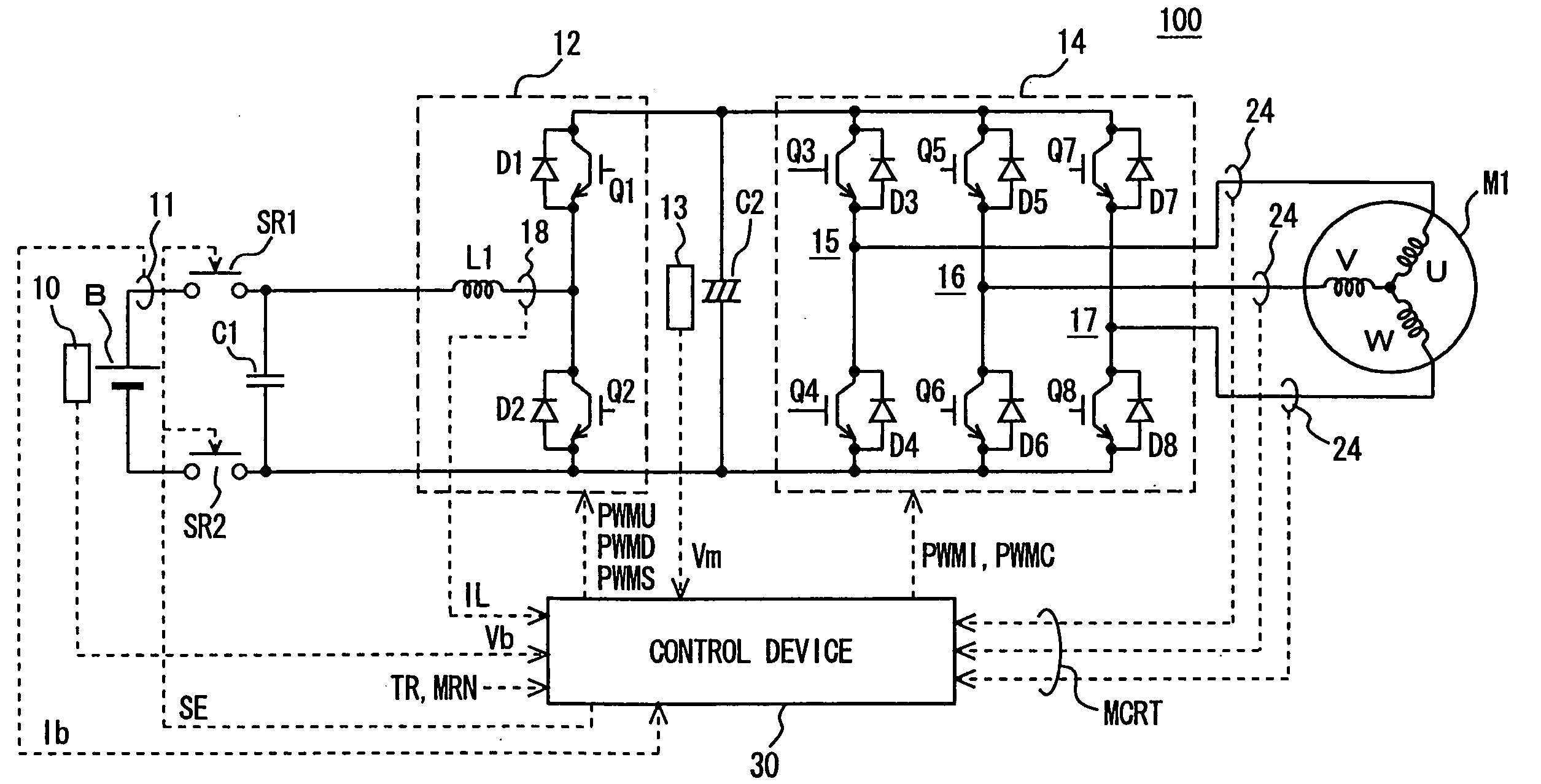
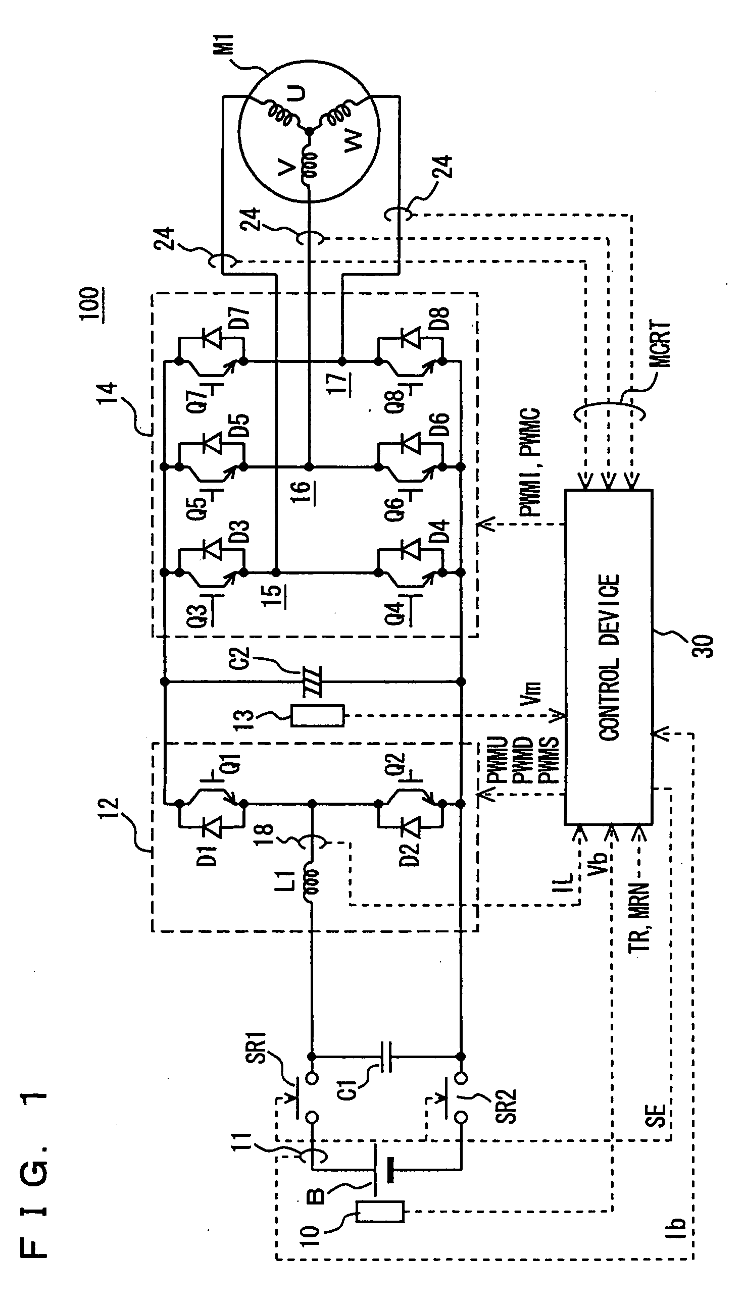
[0102]FIG. 1 is a schematic block diagram of a motor drive apparatus in a first embodiment. With reference to FIG. 1, the first embodiment provides a motor drive apparatus 100 including a battery B, voltage sensors 10, 13, current sensors 11, 18, 24, capacitors C1, C2, an up converter 12, an inverter 14, and a control device 30.

[0103] An alternate current (AC) motor M1 is a drive motor operated to generate a torque applied to drive a driving wheel of a hybrid vehicle or an electric vehicle. Furthermore, AC motor M1 is a motor that can function as a power generator driven by an engine and operates as an electric motor relative to the engine for example to start the engine.

[0104] Up converter 12 includes a reactor L1, NPN transistors Q1, Q2, and diodes D1, D2. Reactor L1 has one end connected to a power supply line of DC power supply B and the other end to a point intermediate between NPN transistors Q1 and Q2, i.e., between the emitter of NPN transistor Q1 and the collector of NPN ...

second embodiment

[0205]FIG. 8 is a block diagram schematically showing the motor drive apparatus in a second embodiment. With reference to the figure, a motor drive apparatus 100A corresponds to motor drive apparatus 100 minus current sensor 11 and having control device 30 replaced with a control device 30A.

[0206] Control device 30A determines from torque command value TR and motor rotation rate MRN from the external ECU and maximum and minimum values ILmax and ILmin of reactor current IL from current sensor 18 in a method, as will be described hereinafter, whether reactor current IL traverses the zero point. If so, control device 30A controls up converter 12 to stop switching to perform an up converting or down converting operation, otherwise control device 30A controls up converter 12 to switch to perform the up converting or down converting operation.

[0207] Control device 30A other than that provides the same function as control device 30.

[0208]FIG. 9 is a block diagram of the FIG. 8 control d...

third embodiment

[0239]FIG. 12 is a block diagram schematically showing the motor drive apparatus in a third embodiment. With reference to the figure, the third embodiment provides a motor drive apparatus 100B corresponding to motor drive apparatus 100 minus current sensors 11, 18 and having control device 30 replace with a control device 30B.

[0240] Control device 30B determines from torque command value TR and motor rotation rate MRN from an external ECU in a method, as will be described hereinafter, whether reactor current IL traverses the zero point. If so, control device 30B controls up converter 12 to stop switching to perform an up converting or down converting operation, otherwise control device 30B controls up converter 12 to switch to perform the up converting or down converting operation.

[0241] Control device 30B other than that provides the same function as control device 30.

[0242]FIG. 13 is a block diagram of the FIG. 12 control device 30B. With reference to the figure, control device...


PUM


Abstract

A control device receives a power supply current from a current sensor and a reactor current from a current sensor and detects a maximum value and a minimum value from the reactor current and from the detected maximum and minimum values and the power supply current determines whether the reactor current traverses the zero point, and if so the control device generates and outputs a signal to an up converter which responds to the signal by stopping switching to perform an up or down converting operation.

Description

TECHNICAL FIELD [0001] The present invention relates generally to motor drive apparatuses, and particularly to motor drive apparatuses capable of reducing switching noise, vehicles having the same mounted therein, and computer readable storage media having a program stored therein to cause a computer to control voltage conversion contributing to reduced switching noise. BACKGROUND ART [0002] Recently, hybrid vehicles and electric vehicles are increasingly noted as environmentally conscious vehicles, and some hybrid vehicles are commercially available. [0003] The hybrid vehicle is a vehicle having as a power source a conventional engine and in addition thereto a DC power supply, an inverter, and a motor driven by the inverter. In other words, the engine is driven to obtain a power source and furthermore the DC power supply provides a DC voltage which is in turn converted by the inverter to an AC voltage which is used to rotate the motor to obtain a power source. [0004] Electric vehic...

Claims


Application Information

Patent Timeline
Patent Type & Authority Applications(United States)
IPC IPC(8): H02P7/06B60L9/18B60L11/18B60L50/15H02M3/155H02M3/158H02M7/48H02P21/05H02P23/04H02P25/22H02P27/06H02P27/08
CPCB60L11/123B60L11/1851B60L2210/20H02M3/1582H02M2001/0009H02M2001/007Y02T10/725Y02T10/6217Y02T10/642Y02T10/7005Y02T10/705Y02T10/7077H02P27/08B60L50/61B60L58/10H02M1/0009H02M1/007Y02T10/62Y02T10/64Y02T10/70Y02T10/72Y02T90/40Y02T10/7072
Inventor NAKAYAMA, HIROSHISAITOU, TOMOHIROMATSUMOTO, TADAICHIKAJIWARA, SHIGETO
Owner TOYOTA JIDOSHA KK
Why Eureka
Try Eureka