Lens system and portable device employing the same

a technology of a portable device and a lens system, which is applied in the field of lenses system and a portable device, can solve the problems of deteriorating the device's reproduction ability, increasing the cost of the portable device, and the outer diameter of the infrared cut filter b>4/b>, so as to prevent redness

Inactive Publication Date: 2006-03-16
SAMSUNG ELECTRONICS CO LTD
View PDF1 Cites 9 Cited by
  • Summary
  • Abstract
  • Description
  • Claims
  • Application Information

AI Technical Summary

Benefits of technology

[0010] The present invention provides a lens system that prevents redness from occurring at the center region of an image as the lens system is miniaturized, and a portable device employing the lens system.

Problems solved by technology

However, light in the near-infrared and infrared regions causes crosstalk that reduces a signal-to-noise ratio of an image pick-up device and thereby deteriorates the device's reproduction ability.
However, when placing the infrared cut filter 4 between the object and the lens system as illustrated in FIG. 1, the outer diameter of the infrared cut filter 4 is increased, thereby increasing the cost of the portable device.
In addition, when disposing the infrared cut filter 4 between the lens system and the image pick-up device 5 as illustrated in FIG. 2, a back focal length (BFL) increases, which increases the size and cost of the image pick-up apparatus.
Thus, the conventional technology presents obstacles to the current trend of producing ever more compact image pick-up apparatuses.
However, the invention of the Japanese patent is costly to implement and therefore not well suited for mass-produced devices.

Method used


Image

  • Lens system and portable device employing the same
  • Lens system and portable device employing the same
  • Lens system and portable device employing the same

Examples


first embodiment

[0025]FIG. 3 is a schematic diagram of a light path for explaining the theory of the present invention. FIG. 4 is a schematic diagram of a lens system and an image pick-up apparatus employing the lens system according to the present invention.

[0026] In order to further miniaturize already-small cameras, especially those installed in portable devices such as mobile phones, a lens system included in the camera has to be miniaturized. However, as a consequence of miniaturizing the lens system, an angle at which light is incident on the lens system increases.

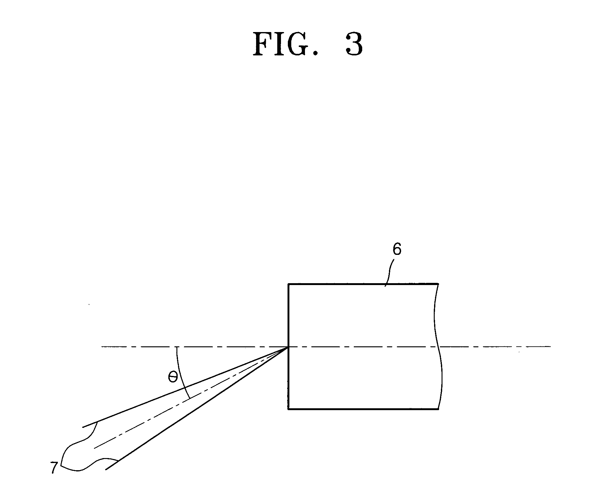
[0027] Here, as illustrated in FIG. 3, light reflected from an object is incident on a lens system 6 in the form of a light cone 7, which is similar to a circular cone. In this case, an incident angle □ of light traveling along the axis of the light cone 7 is called a telecentric angle, or chief ray angle. The telecentric angle is important because the light on the axis of the light cone 7 determines the form of a resulting image w...

second embodiment

[0036]FIG. 5 is a schematic diagram of a lens system and an image pick-up device according to the present invention.

[0037] In the present embodiment, the lens system includes three lenses in the order of a first lens 21 having a positive refractive power, a second lens 22 having a positive refractive power, and a third lens 23 having a negative refractive power, from the direction in which light enters the lens system from outside. Also, an infrared cut filter 24 is interposed between the second lens 22 and the third lens 23.

[0038] As previously described, the smaller a telecentric angle of light incident on an infrared cut filter included in a lens system, the better. As illustrated in FIG. 5, a telecentric angle of light incident on the infrared cut filter 24 can be smaller, since the light path of the incident light is changed due to the first and second lenses 21 and 22, before being incident on the infrared cut filter 24. In this way, image distortion can be further reduced.

[...

third embodiment

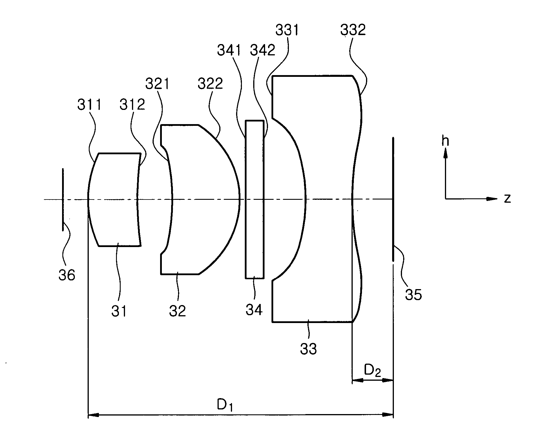
[0046]FIG. 8 is a schematic diagram of a lens system and an image pick-up device employing the lens system according to the present invention.

[0047] The lens system in the present embodiment includes three lenses: a first lens 31, a second lens 32, and a third lens 33. The first lens 31 has 2nd and 3rd surfaces 311 and 312, the second lens 32 has 4th and 5th surfaces 321 and 322, and the third lens 33 has 8th and 9th surfaces 331 and 332. An infrared cut filter 34, which has 6th and 7th surfaces 341 and 342, is disposed between the second lens 32 and the third lens 33. An aperture 36 is disposed in front of the lens system and an image pick-up device 35.

[0048] If D1 denotes a distance from the 2nd surface 311, on which light is first incident, to the image pick-up device 35, and D2 denotes a distance from the 9th surface 332, through which light is output from the lens system to the image pick-up device 35, it is preferable that D1 and D2 be made to satisfy the following inequality...


PUM


Abstract

A lens system and a portable device employing the lens system are provided. The lens system includes at least three lenses and an infrared cut filter disposed between any of the lenses to prevent redness from occurring at a center region of an image as the lens system is miniaturized. An angle ⊖1 at which light is incident on the infrared cut filter satisfies 14°≦θ1≦16°.

Description

[0001] This application claims the priority of Korean Patent Application No. 2004-65880, filed on Aug. 20, 2004, in the Korean Intellectual Property Office, the disclosure of which is incorporated herein in its entirety by reference. BACKGROUND OF THE INVENTION [0002] 1. Field of the Invention [0003] The present invention relates to a lens system and a portable device, and more particularly, to a lens system that prevents redness from occurring at the center region of an image as the lens system is miniaturized, and a portable device employing the lens system. [0004] 2. Description of the Related Art [0005] Generally, image pick-up devices such as charge coupled devices (CCDs) or complementary metal oxide semiconductors (CMOS) used in, for example, cameras, react to light even in the near-infrared region beginning at a wavelength of about 700 nm and in the infrared region. However, light in the near-infrared and infrared regions causes crosstalk that reduces a signal-to-noise ratio ...

Claims


Application Information

Patent Timeline
Patent Type & Authority Applications(United States)
IPC IPC(8): G02B9/12
CPCG02B13/0035G02B9/12G02B1/041G02B5/281G02B13/18H04M1/0264G03B30/00
Inventor LEE, KI-WOO
Owner SAMSUNG ELECTRONICS CO LTD
Why Eureka
Try Eureka