Infrared sensor, infrared gas detector and infrared ray source

Inactive Publication Date: 2006-03-23
DENSO CORP +1
View PDF10 Cites 32 Cited by
  • Summary
  • Abstract
  • Description
  • Claims
  • Application Information

AI Technical Summary

Benefits of technology

[0023] In the conventional infrared ray source having the above construction (solely or infrared gas detector), corrosion of the infrared ray source pad portion is prevented by applying the can-sealing structure as in the case of the infrared sensor described above. However, if parylene is applied as protection film, the whole surface at one surface side of the substrate surface containing not only the light source portion, but also the formation area on which the resistor is formed can be protected by the same action and effect as the first aspect. Accordingly, the can-sealing structure is not required, and thus the body can be miniaturized, so that the construction can be simplified. Furthermore, the energy amount of infrared ray transmitted thro

Problems solved by technology

However, in the case of the above structure, the detecting element is sealed by the stem and the cap, and thus it is difficult to miniaturize the body of the infrared sensor.
However, in this case, it is necessary to provide a dam and th

Method used


Image

  • Infrared sensor, infrared gas detector and infrared ray source
  • Infrared sensor, infrared gas detector and infrared ray source
  • Infrared sensor, infrared gas detector and infrared ray source

Examples


first embodiment

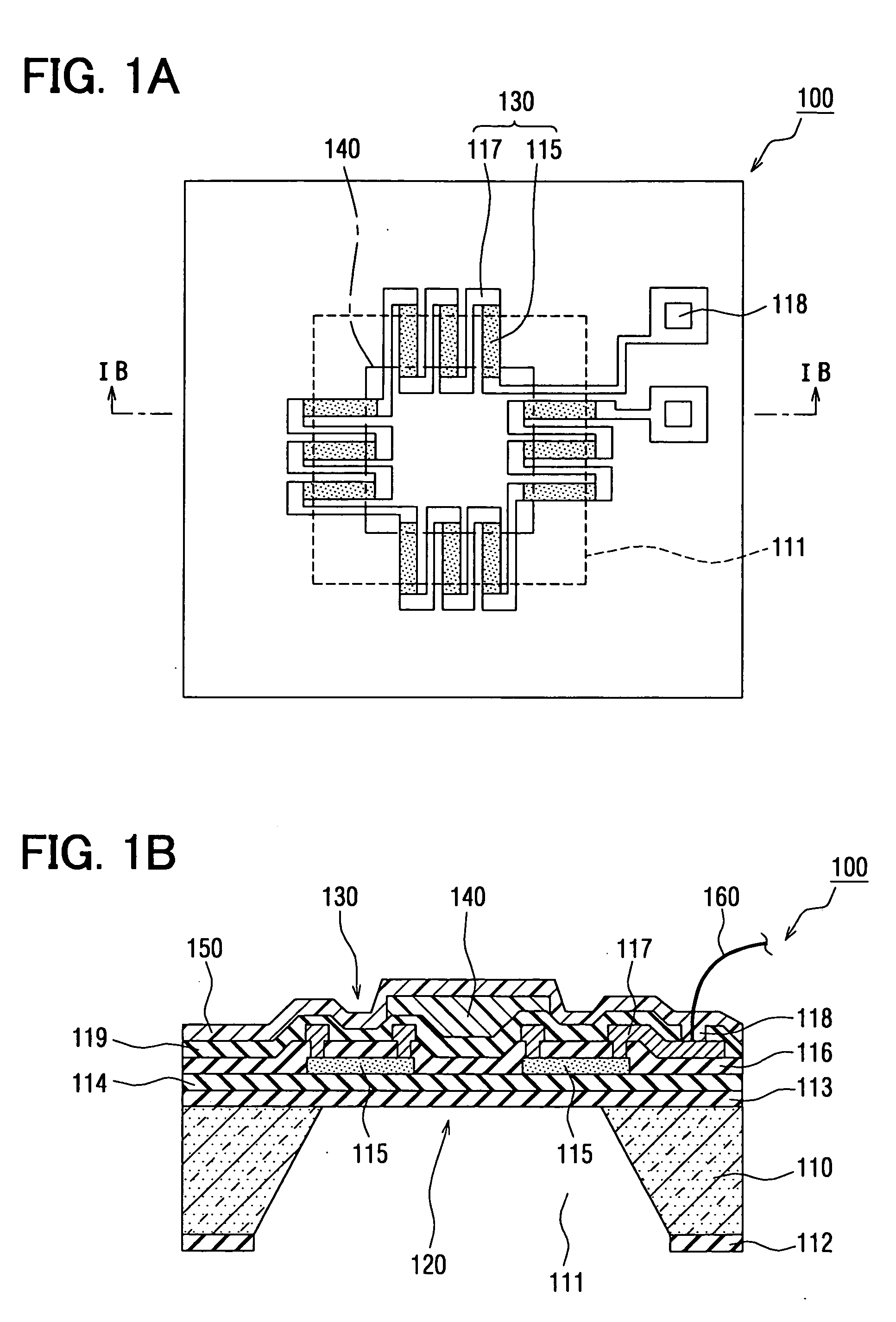
[0033]FIGS. 1A and 1B are diagrams showing the schematic construction of an infrared sensor according to a first embodiment, wherein FIG. 1A is a plan view and FIG. 1 B is a cross-sectional view taken along IB-IB of FIG. 1A. In FIG. 1A, a detecting element and a wire portion for connecting the detecting element and electrodes are illustrated for the sake of convenience. A rectangular area surrounded by a broken line represents a formation area on the upper surface of a cavity portion on the upper surface of the substrate, and a rectangular surrounded by a one-dotted chain line represents a formation area of infrared ray absorption film.

[0034] As shown in FIG. 1B, an infrared sensor 100 has a substrate 110, a membrane 120 as a small-thickness portion provided to the substrate 110, a detecting element 130 for detecting infrared rays, infrared-ray absorption film 140, and a second protection film 150 formed of parylene. The second protection film 150 is a feature portion of this embod...

second embodiment

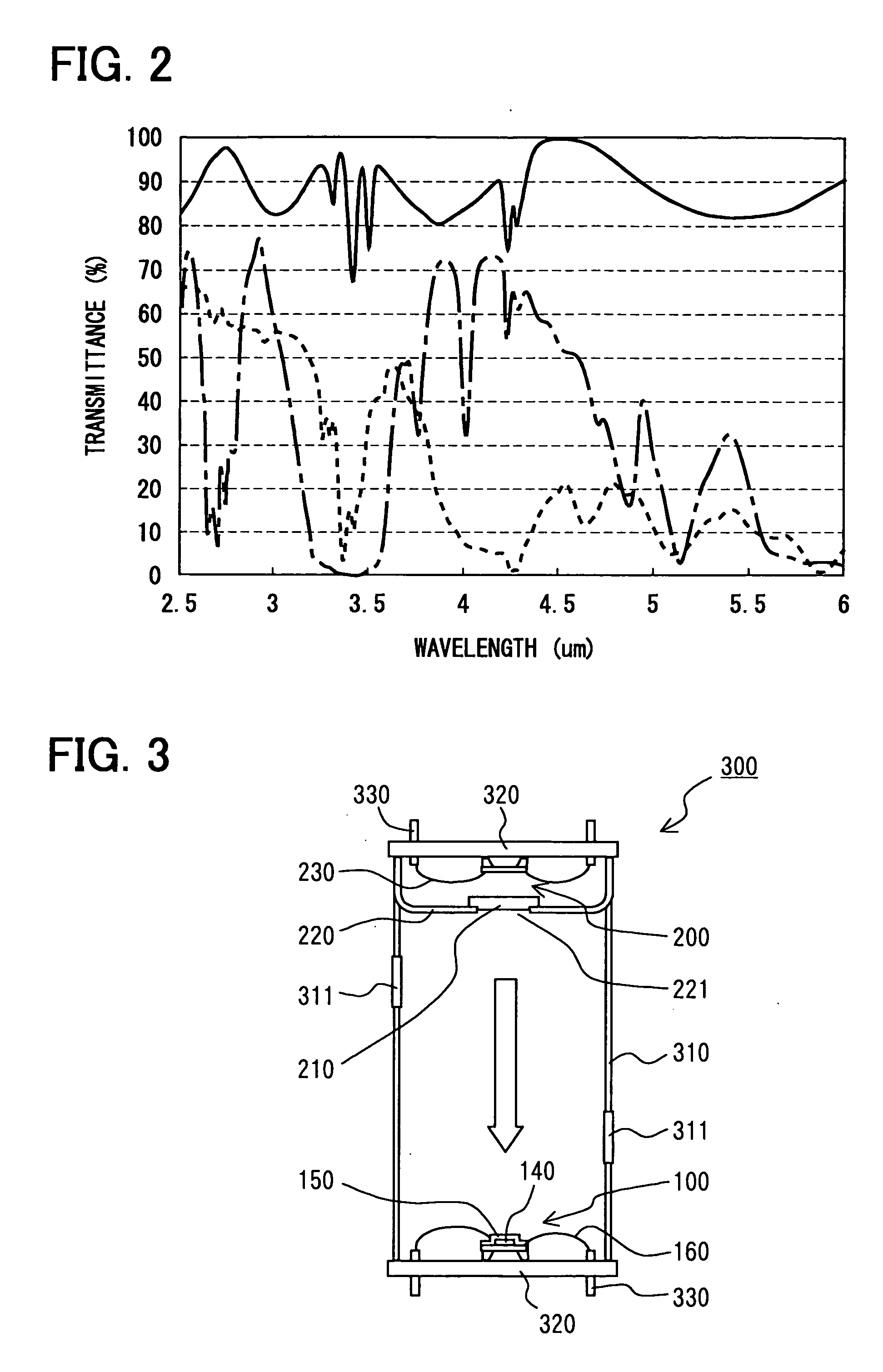
[0064] Next, a second embodiment will be described with reference to FIG. 3. FIG. 3 is a diagram showing the schematic construction of an infrared gas detector according to this embodiment.

[0065] In the second embodiment, the infrared sensor 100 of the first embodiment is applied to a gas detector, and it has many common parts to the first embodiment. Therefore, the detailed description on the common parts is omitted from the following description, and different parts will be mainly described.

[0066] As shown in FIG. 3, the infrared sensor 100 of the first embodiment may constitute an infrared ray detection type gas detector 300 (hereinafter referred to as gas sensor) in combination with an infrared ray source 200 for radiating infrared rays to the infrared ray sensor 100.

[0067] In this case, the infrared sensor 100 has second protection film 150 on the surface thereof, and thus the can-sealing structure which has been hitherto required is unnecessary. Therefore, in this embodimen...

third embodiment

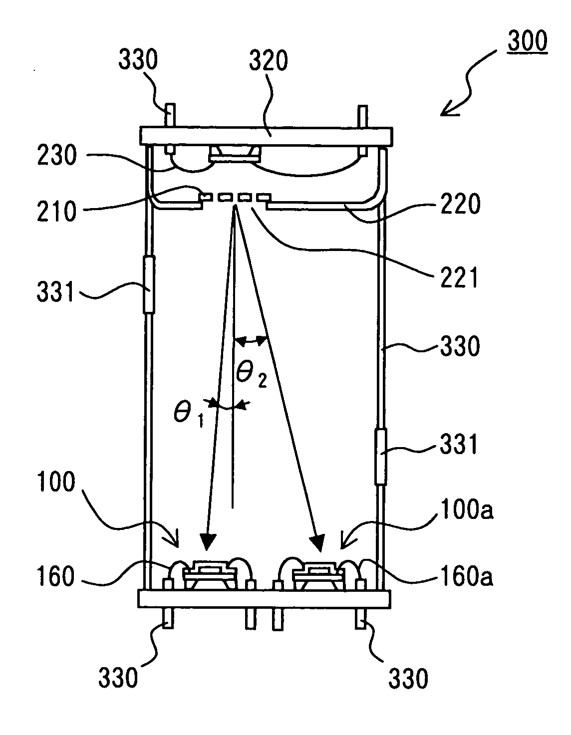
[0075] Next, a third embodiment will be described with reference to FIG. 4. FIG. 4 is a diagram showing the schematic construction of a gas sensor 300 according to this embodiment.

[0076] The gas sensor according to the third embodiment has many common parts to the infrared sensor 100 of the first embodiment and the gas sensor 300 of the second embodiment, and the detailed description on the common parts is omitted from the following description, and different parts will be mainly described.

[0077] As shown in FIG. 4, the gas sensor 300 of this embodiment has a reference infrared sensor 100a for absorbing infrared ray having a specific wavelength which is not overlapped with the infrared-ray absorption wavelength of the measurement target gas and outputting a reference signal corresponding to the absorption amount of the infrared ray, and further corrects the detection signal of the infrared sensor 100 on the basis of the reference signal.

[0078] The reference infrared sensor 100a i...


PUM


Abstract

An infrared sensor includes a substrate, a membrane as a small-thickness portion formed on the substrate, a detecting element for generating a detection signal on the basis of temperature variation occurring when receiving infrared rays, at least a part thereof being formed on the membrane, and an infrared ray absorption film formed on the membrane so as to cover at least a part of the detecting element. The detecting element is externally electrically connected through a sensor pad portion provided at an end portion of the detecting element. A substrate surface including the sensor pad portion and the infrared ray absorption film is coated by a protection film made of parylene.

Description

CROSS REFERENCE TO RELATED APPLICATION [0001] This application is based upon, claims the benefit of priority of, and incorporates by reference the contents of Japanese Patent Application No. 2004-258669 filed on Sep. 6, 2004. FIELD OF THE INVENTION [0002] The present invention relates to an infrared sensor for detecting infrared rays, an infrared gas detector containing the infrared sensor for detecting the concentration of measurement target gas by using infrared rays, and an infrared light ray source for irradiating infrared rays to the infrared sensor. BACKGROUND OF THE INVENTION [0003] For example, JP-A-2003-270047 discloses an infrared sensor having a detecting element for generating a detection signal on the basis of temperature variation occurring when the detecting device detects infrared rays. According to the infrared sensor disclosed in the above publication, a sensor element (detecting element) is air-tightly sealed by a stem and a cap having an opening portion closed by...

Claims


Application Information

Patent Timeline
IPC IPC(8): G01J5/02G01J1/02G01J5/12G01J5/16G01N21/01G01N21/35G01N21/3504H01L35/32H01L35/34
CPCG01J5/10G01J5/12G01J5/20H01L2224/48091H01L37/00G01N21/3504H01L2924/00014H10N15/00
Inventor UCHIDA, KOJITANAKA, MASAAKIYOSHIDA, TAKAHIKO
Owner DENSO CORP
Why Eureka
Try Eureka