
Ion implanters having an arc chamber that affects ion current density

a technology of ion current density and arc chamber, which is applied in the field of ion implanters, can solve the problems of loss of thermoelectrons in arc chambers, and achieve the effect of reducing the loss of thermoelectrons

Active Publication Date: 2006-03-23
SAMSUNG ELECTRONICS CO LTD
View PDF2 Cites 4 Cited by
  • Summary
  • Abstract
  • Description
  • Claims
  • Application Information

AI Technical Summary

Benefits of technology

[0006] Embodiments of the present invention provide ion implanters including an arc chamber that improves ion current density.
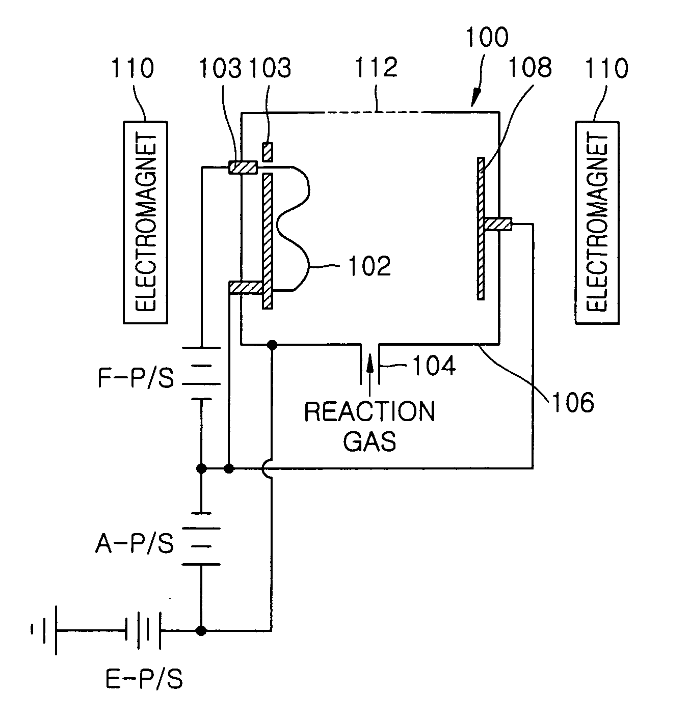
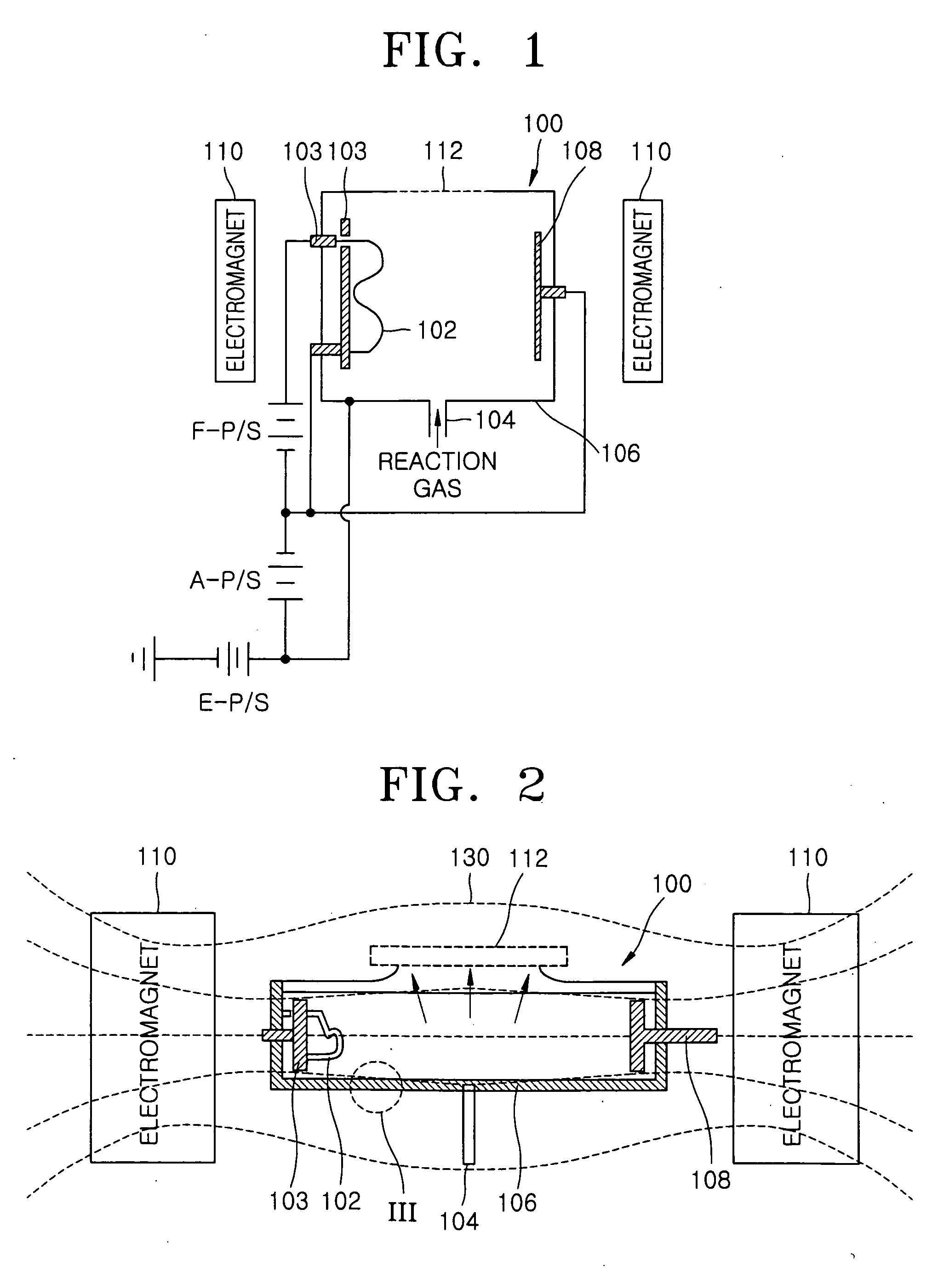
[0007] According to some embodiments of the present invention, the arc chamber includes at least a first inner region and a second inner region, an electron emitting device disposed in the arc chamber adjacent the first inner region and adapted to emit electrons, an electron returning device disposed in the arc chamber adjacent the second inner region and adapted to return at least some of the electrons emitted from the electron emitting device into the second inner region and an electric field and magnetic field generating device adapted to provide a magnetic field to the arc chamber, wherein at least one inner wall of the arc chamber has a convex surface. In some embodiments, the ion implanter includes an arc chamber including an interior region including a filament in one inner region of the interior region adapted to emit thermoelectrons and a repeller in a second inner region of the interior region positioned opposite the filament and adapted to prevent consumption of at least some of the thermoelectrons.
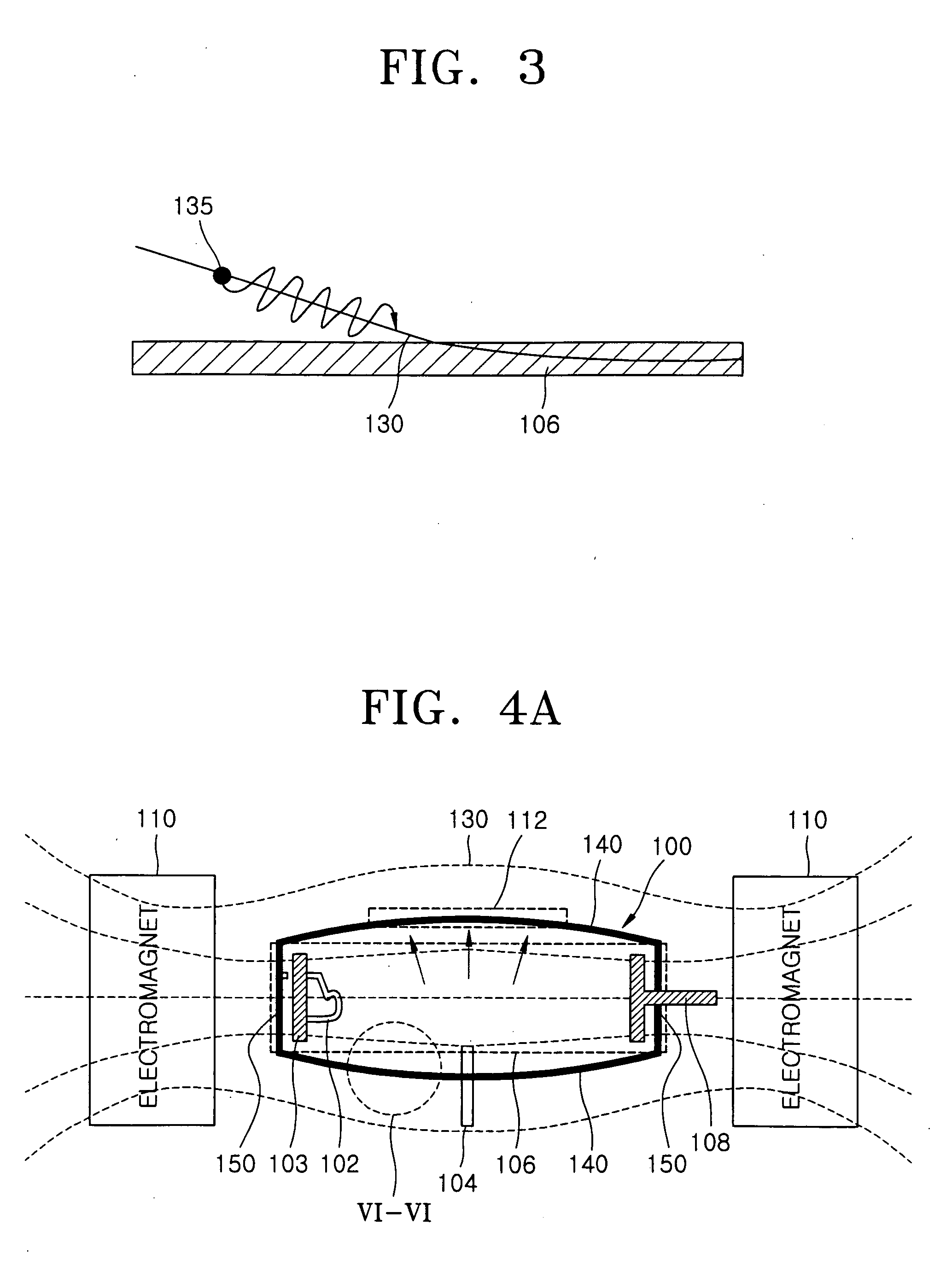
[0008] Some embodiments of the present invention further provide an ion implanter including an arc chamber, as described above, further including an electric field and magnetic field generating device adapted to direct outward lines of magnetic force along at least one inner wall of the arc chamber in a convex distribution pattern, wherein the at least one inner wall of the arc chamber is disposed parallel-to the lines of magnetic force applied between the electron emitting device and the electron returning device. In some embodiments, the ion implanter includes an electromagnet installed outside the arc chamber including the filament and the repeller, and the electromagnet thereby enables lines of magnetic force to distribute in an outwardly convex pattern.
[0010] In some embodiments of the present invention, the ion implanter includes an arc chamber, an electron emitting device, an electron returning device, and an electric field and magnetic field generating device disposed external to the arc chamber and adapted to direct outward lines of magnetic force in a convex distribution pattern in a direction away from the interior of the arc chamber, wherein the arc chamber includes at least one inner wall having a convex surface thereby reducing the loss of electrons in a region where the lines of magnetic force intersect the at least one inner wall.
[0012] According to some embodiments of the present invention, the ion implanter described above may further include a gas supply system adapted to direct a source gas into the arc chamber, and an ion extraction outlet extending through a sidewall of the arc chamber adapted to extract ions from the arc chamber, wherein a positive voltage is applied to at least one inner wall of the arc chamber to accelerate electron emission from an electron emitting device thereby providing energy to the electrons for ionization of the source gas, and wherein the at least one inner wall of the arc chamber has a convex surface thereby reducing the loss of thermoelectrons in a region where the lines of magnetic force intersect the at least one inner wall.

Problems solved by technology

However, in a conventional ion implanter, a number of thermoelectrons emitted from a filament in an arc chamber may be lost through a body of the arc chamber before colliding with a reactant gas.

Method used


Image

  • Ion implanters having an arc chamber that affects ion current density
  • Ion implanters having an arc chamber that affects ion current density
  • Ion implanters having an arc chamber that affects ion current density

Examples


Embodiment Construction

[0024] The invention is described more fully hereinafter with reference to the accompanying drawings, in which embodiments of the invention are shown. This invention may, however, be embodied in many different forms and should not be construed as limited to the embodiments set forth herein. Rather, these embodiments are provided so that this disclosure will be thorough and complete, and will fully convey the scope of the invention to those skilled in the art. In the drawings, the size and relative sizes of layers and regions may be exaggerated for clarity.

[0025] It will be understood that when an element or layer is referred to as being “on”, “connected to” or “coupled to” another element or layer, it can be directly on, connected or coupled to the other element or layer or intervening elements or layers may be present. In contrast, when an element is referred to as being “directly on,”“directly connected to” or “directly coupled to” another element or layer, there are no interveni...


PUM


Abstract

The present invention can provide ion implanter devices including an arc chamber including at least a first inner region and a second inner region, an electron emitting device disposed in the arc chamber adjacent the first inner region and adapted to emit electrons, an electron returning device disposed in the arc chamber adjacent the second inner region and adapted to return at least some of the electrons emitted from the electron emitting device into the second inner region; and an electric field and magnetic field generating device adapted to provide a magnetic field to the arc chamber, wherein at least one inner wall of the arc chamber has a convex surface.

Description

CROSS REFERENCE TO RELATED APPLICATION [0001] This application claims priority from Korean Patent Application No. 10-2004-0075116, filed Sep. 20, 2004, the disclosure of which is incorporated herein by reference in its entirety. FIELD OF THE INVENTION [0002] The present invention relates to ion implanters, and more particularly, to ion implanters having a configuration that affects ion current density. BACKGROUND OF THE INVENTION [0003] Generally, fabrication processes of semiconductor devices may involve an ion implantation process. During the ion implantation process, p-type impurities, such as boron (B) and indium (In), or n-type impurities, such as phosphorus (P) and arsenic (As), may be ionized and implanted into a silicon wafer. Such an ion implantation process may be used because it may be less difficult to control the concentration of impurities implanted into a silicon wafer. [0004] An ion implanter for implementing the ion implantation process may include an arc chamber fr...

Claims


Application Information

Patent Timeline
IPC IPC(8): H01J37/08
CPCH01J27/08H01J2237/31703H01J2237/082H01J37/08H01J37/30H01L21/265
Inventor KWON, UI-HUIKEUM, GYEONG-SUCHUNG, WON-YOUNGCHA, KWANG-HOKIM, YOUNG-TAECHAE, SEUNG-KIWON, JAI-HYUNGPARK, YOUNG-KWANKIM, TAI-KYUNG
Owner SAMSUNG ELECTRONICS CO LTD
Learn More