Power converter controlling apparatus and method providing ride through capability during power interruption in a motor drive system

a technology of power converters and control apparatuses, applied in the direction of motor/generator/converter stoppers, dynamo-electric converter control, stopping arrangements, etc., can solve the problems of difficult resynchronization and still required soft star

Inactive Publication Date: 2006-03-23
HONEYWELL INT INC
View PDF35 Cites 22 Cited by
  • Summary
  • Abstract
  • Description
  • Claims
  • Application Information

AI Technical Summary

Benefits of technology

[0005] In one respect, the present invention is a method of controlling a power converter of a motor drive system, the method comprising: controlling the power converter during a first operating mode by applying a current control scheme, which sets power converter commands to control torque current flowing from the power converter to the motor to achieve desired motor speed; and initiating a second op

Problems solved by technology

Because such systems will lose rotor position information once gating is disabled and the contactors are opened, it is difficult to achieve resynchronization after a power interruption.
Even w

Method used


Image

  • Power converter controlling apparatus and method providing ride through capability during power interruption in a motor drive system
  • Power converter controlling apparatus and method providing ride through capability during power interruption in a motor drive system
  • Power converter controlling apparatus and method providing ride through capability during power interruption in a motor drive system

Examples


Embodiment Construction

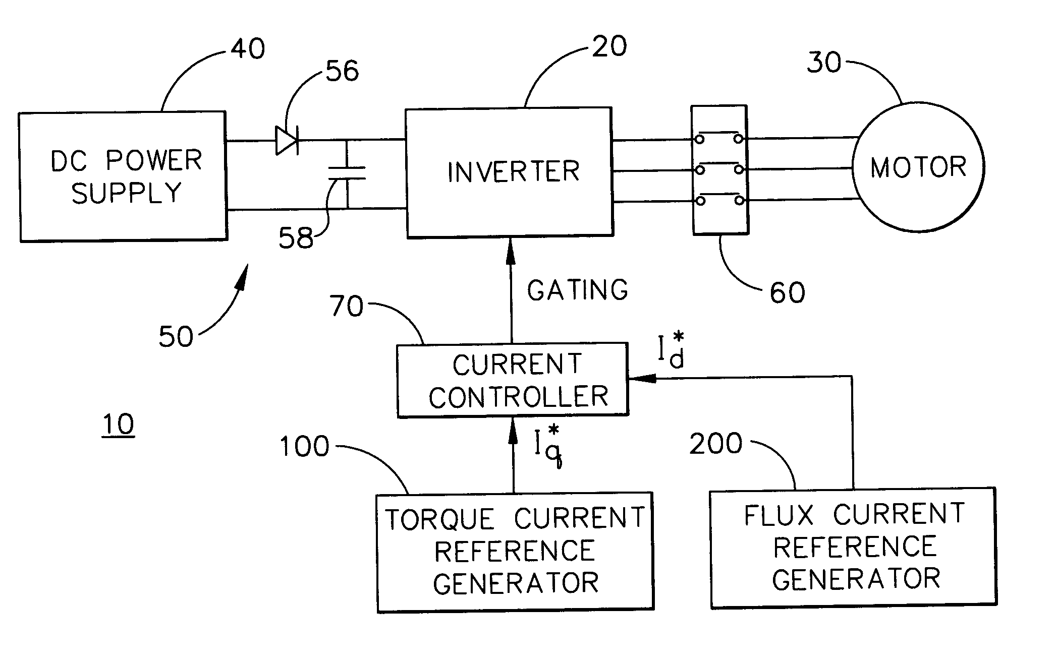
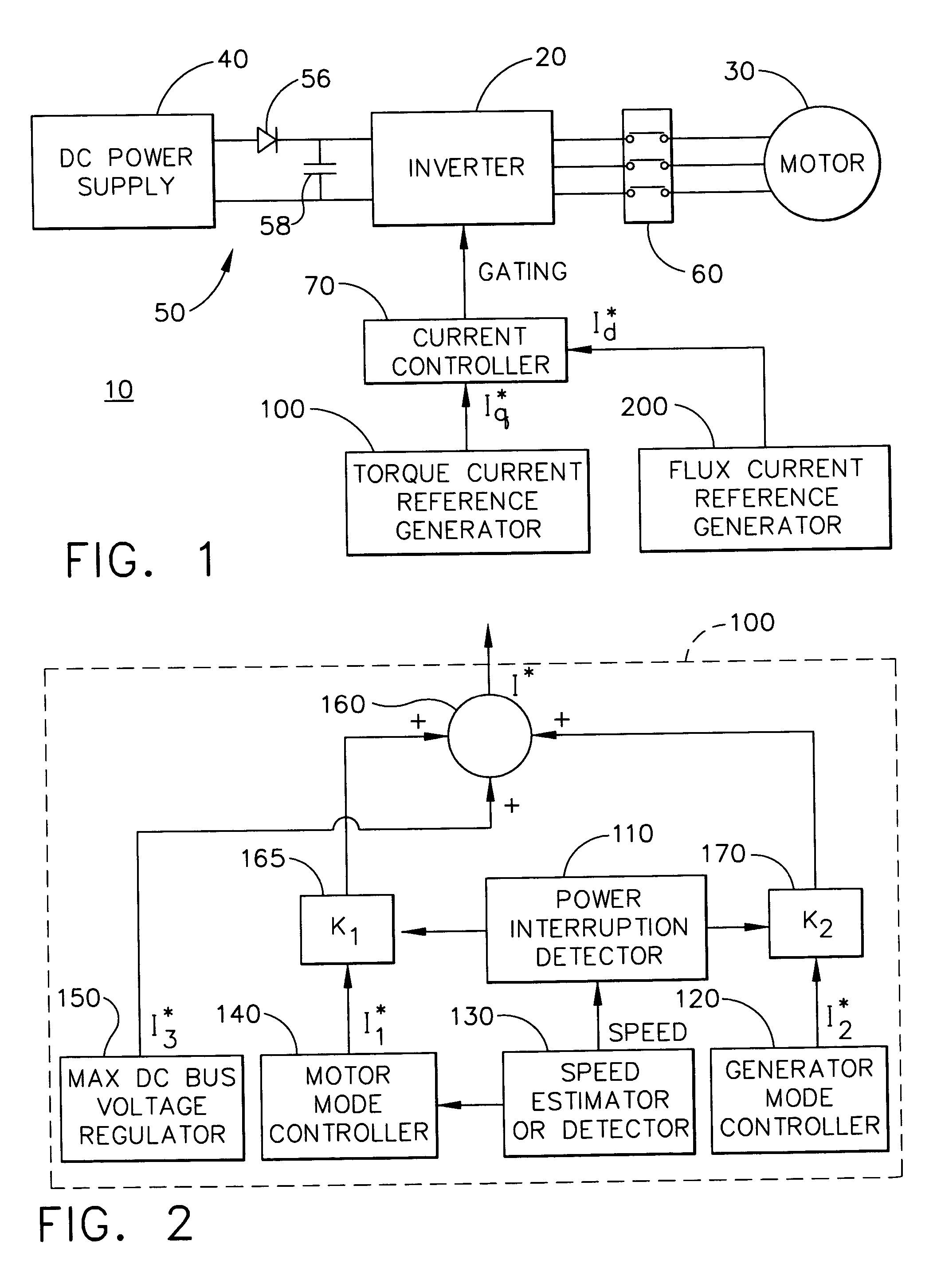
[0013] Embodiments of the present invention are more specifically set forth in the following description, with reference to the appended drawings. In the following description and accompanying drawings like elements are denoted with similar reference numbers. Further, well-known elements and related explanations are omitted so as not to obscure the inventive concepts presented herein.

[0014] In one general aspect of the present invention, a voltage source inverter (VSI) based motor drive system selectively initiates generator mode control, during power interruption, to transition the motor from a motor mode to a generator mode. In one embodiment, during generator mode, the mechanical energy on the motor shaft is used to boost up and maintain a DC link capacitor voltage at a certain level, which is slightly higher than the normal operation DC link voltage. This is done to limit the inrush current when the input power recovers. Only a small amount of energy is required to compensate f...


PUM


Abstract

A method of controlling a power converter (20) of a motor drive system (10)controls the power converter (20) during a first operating mode by applying a current control scheme, which sets power converter commands to control torque current flowing from the power converter (20) to the motor (30) to achieve desired motor speed; and initiates a second operating mode when power supply to the power converter (20) is interrupted. The second operating mode includes controlling negative torque current between the power converter (20) and the motor (30) so that mechanical energy from the motor (30) charges an element (58) on a power supply side of the power converter (20). The first operating mode is resumed when the input power recovers. Torque current between the power converter (20) and the motor (30) is also controlled to limit a maximum transient DC bus voltage.

Description

RELATED APPLICATION [0001] This application claims priority under 35 U.S.C. § 119(e) of Provisional Application No. 60 / 611,298 filed Sep. 21, 2004, the entire contents of which are herein incorporated by reference.FIELD OF THE INVENTION [0002] The present invention relates to electrical power conversion, and more particularly to a power converter controlling apparatus and method proving ride through capability during power interruption in a motor drive system. BACKGROUND OF THE INVENTION [0003] An exemplary motor drive system includes the following main components: a motor, such as a three-phase permanent magnet synchronous motor (PMSM); a multi-phase power inverter; a DC power supply; and a current controller, which generates gating signals for output to the power inverter. The power inverter converts DC power from power supply into multi-phase AC power, e.g., utilizing a configuration of insulated-gate bipolar transistors (IGBTs), as a function of rotor position / speed. Rotor posit...

Claims


Application Information

Patent Timeline
IPC IPC(8): H02P7/42H02P27/00
CPCH02P6/08H02P29/025H02P23/0036H02P6/24H02P23/0004
Inventor MA, JACK DAMINGZHOU, GEORGE YOUWANG, ZHENG
Owner HONEYWELL INT INC
Why Eureka
Try Eureka