MIMO communication system and data link

a communication system and a data link technology, applied in the field of mimo communication system and data link, can solve the problems of high fidelity analogue signals that cannot be transmitted through a practical ultrasonic acoustic data link without, the bond line is extremely vulnerable to temperature-induced delamination, and the thin bond layer is unrealistic to achiev

Active Publication Date: 2020-06-25
BAE SYSTEMS PLC
View PDF8 Cites 0 Cited by
  • Summary
  • Abstract
  • Description
  • Claims
  • Application Information

AI Technical Summary

Benefits of technology

[0028]Embodiments of the solution disclosed herein can provide a practical implementation geometry for realising very high data rate acoustic MIMO through either a solid barrier, or a fluid containing barrier. The maximum barrier thickness through which data can be transmitted successfully is determined by the required Bit Error Rate (BER) performance for the communication system. Before Forward Error Correction (FEC), the BER might be as bad as 5×10⁻². Typically, after Forward Error Correction (FEC), a BER of better than 10−7, is normally sought. The BER for its part will be a function of both the Forward Error Correction algorithms used either individually or collectively (e.g. a combination of Viterbi FEC and a Reed Solomon FEC may be used), and the complexity of the signal modulation scheme. Ultimately the Signal to Noise Ratio (SNR) for each COFDM frequency tone at the electronics inputs of the individual elements of the receiver array will limit the maximum barrier thickness that can be supported.
[0053]A live electrode of each of the plurality of first (and second) transducers may be rectangular in shape, or may be elliptical or diamond in shape. A shortest dimension of the rectangular (or elliptical or diamond) shape may be parallel to a main axis of the plurality of transducers. This can ensure that the highest far field diffraction occurs along the axis of the transducers to provide a particularly rich multipath signal channel along this axis.

Problems solved by technology

Consequently, high fidelity analogue signals cannot be transmitted through a practical ultrasonic acoustic data link without the ghosting that is caused by multipath interference signals from bonds that form intermediate physical interfaces.
Such thin bond layers are not realistic to achieve, particularly outside a cleanroom environment, and the resulting bond line would be extremely vulnerable to temperature induced delamination.
By comparison, acoustic multipath signals can reverberate for much longer due to the comparatively low speed of sound.
This limits the selection of possible COTS signal modulation schemes using off the shelf components.
The data rate of any ultrasonic data link will be limited ultimately by the frequency dependent slope of acoustic attenuation across the link's frequency band of operation.
This restriction reduces the required dynamic range of the ADC's and DAC's that are used in the digital electronics to create and decode COFDM waveforms.
This can be a problem in a MIMO-OFDM system since it requires a rich multipath environment in order to operate effectively.
Destructive signal interference between different ‘time of flight’ signals is likely to yield signal fade out at specific frequencies.
This effect for a Single Input Single Output (SISO) communication system, with one antenna at each end of the communications link, can lead to an unacceptably high Bit Error Rates (BER) if too many frequency tones are affected.
It is not practical to achieve this separation for more than 2 antennae on a conventional mobile phone handset operating at 2.5 GHz.
There must also be low signal correlation between the received signals; otherwise the separate data streams cannot be fully independent and the supportable data rate falls.
In the acoustic domain, acoustic MIMO is known, but it is much less well developed technologically.

Method used


Image

  • MIMO communication system and data link
  • MIMO communication system and data link
  • MIMO communication system and data link

Examples


Embodiment Construction

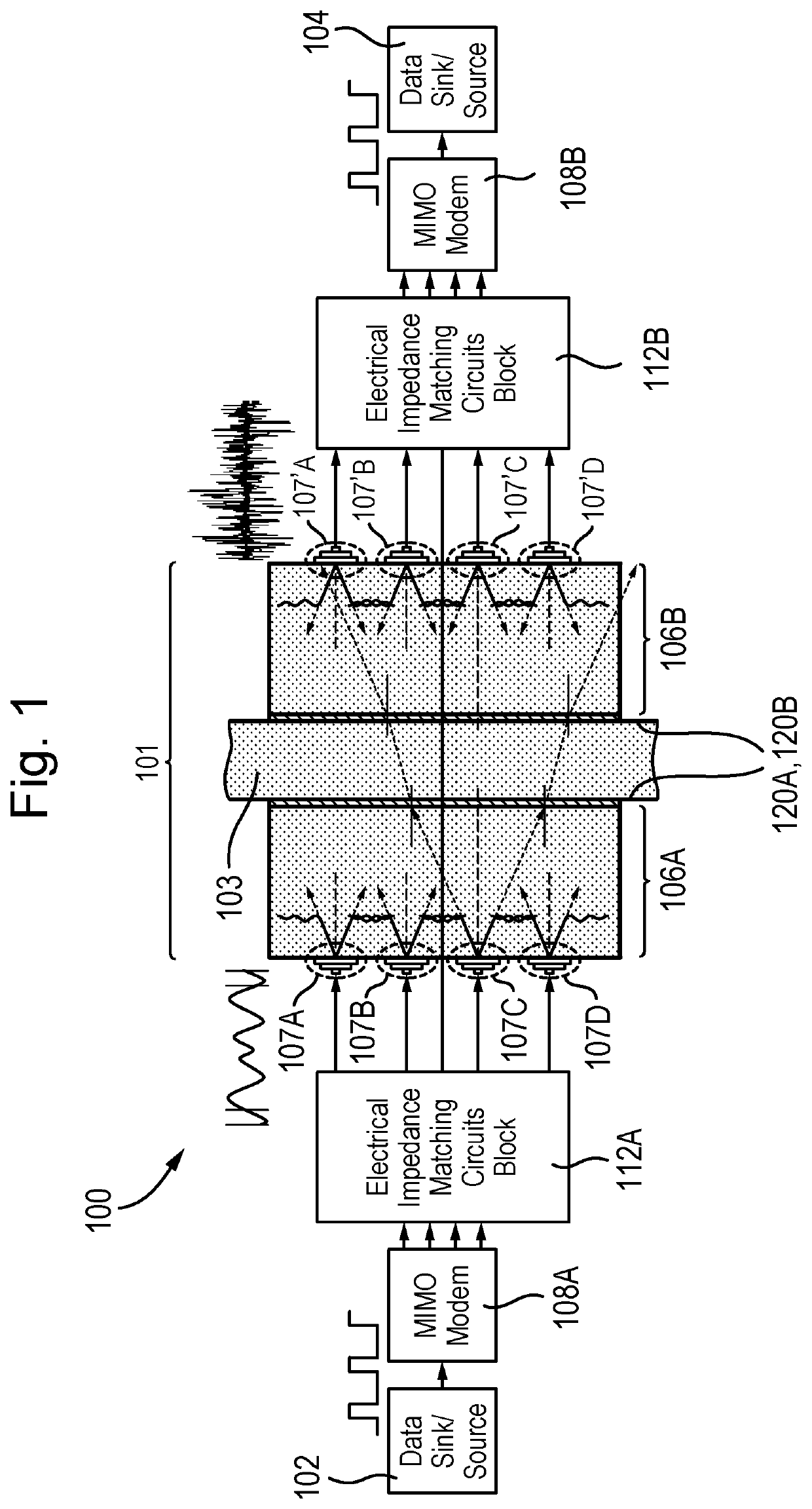
[0079]FIG. 1 is a block diagram of an example acoustic MIMO communication system 100. The diagram shows the top level blocks that support the transmission of data from a data source 102 on the left-hand side, via an acoustic MIMO data link 101, to a data sink 104 on the right-hand side. The example system is intrinsically symmetrical (although in practice there may be lateral offsetting of some components) and could alternatively be used to transmit data from right to left, with the roles of the source 102 and sink 104 being reversed. The example embodiment is intended to provide high speed digital communications through a thin, e.g. 10 mm thick, wall / barrier 103 of ballistic grade aluminium over the frequency range 80 MHz to 120 MHz. Using an LTE based signal modulation scheme the embodiment can be capable of supporting data transfer rates of greater than 300 Mbps.

[0080]Simultaneous full duplex data transmission cannot be supported over the same frequency band of operation in the e...


PUM


Abstract

A data link (101) for a MIMO communication system (100) comprises a first transceiver device (106A) comprising a body (109A) having a transducer mounting surface near or at which is mounted a plurality of first transducers (107A-107D) configured to, in use, receive and convert a plurality of electrical waveforms to a respective plurality of acoustic signals. A first bonding layer (120A) bonds a barrier mounting surface of the body of the first transceiver device to a barrier (103). The data link further comprises a second transceiver device (106B) comprising a body (109B) and a plurality of second transducers (107′A-107′D) configured to receive and convert the plurality of acoustic signals transmitted through the barrier to a respective plurality of electrical waveforms. A second bonding layer (120B) bonds a barrier mounting surface of the body of the second transceiver to the barrier.

Description

FIELD OF THE INVENTION[0001]The present invention relates to acoustic Multiple Inputs Multiple Outputs (MIMO) communication systems and a data link for MIMO communication systems.BACKGROUND[0002]Acoustic signal transmission across a barrier for any realistic deployable ultrasonic communication system will normally be characterised by high levels of signal multipath. Such multipath is caused by reflections off intermediate interfaces, such as any physical interface between two different media of different acoustic impedance in the communications channel. Any adhesive bond between such interfaces will typically be highly reflective.[0003]Adhesive bonds between most structural elements in an ultrasonic communications system will by necessity be acoustically thick; in part to avoid bond delamination caused by differential shear stresses during thermal cycling, and also to reduce the impact of particulate contamination on the thickness of the bond. Consequently, high fidelity analogue si...

Claims


Application Information

Patent Timeline
Patent Type & Authority Applications(United States)
IPC IPC(8): H04B11/00H04B1/40H04L27/00
CPCH04B11/00H04L27/0002H04B1/40G10K11/02H04R17/00G01S7/521B06B1/0618B06B1/06H04R17/10B06B1/0644G01N29/28G10K11/002B06B2201/55G01N2291/0231H10N30/00
Inventor KENT, LIONEL WILLIAM
Owner BAE SYSTEMS PLC
Why Eureka
Try Eureka