ND filter of optical film laminate type with carbon film coating

Inactive Publication Date: 2006-03-23
NIDEC COPAL CORPORATION
View PDF4 Cites 7 Cited by
  • Summary
  • Abstract
  • Description
  • Claims
  • Application Information

AI Technical Summary

Benefits of technology

[0016] According to the present invention, the ND filter is composed of a light-absorbing film and a dielectric film laminated on a transparent substrate, in which a carbon film is formed as a protective film. As generally known, the carbon film has the diamond structure, the DLC (Diamond Like Carbon) structure, or the graphite structure. The carbon film excels in the abrasion resistance because of the dense composition and a high degree of hardness. Compared to inorganic insulative dielectric films, the carbon film shows a low surface resistance and has an anti-electrostatic property. The carbon film having these characteristics is formed as an outmost layer of the ND filter, and makes it possible to provide a product that is scratch resistant and hardly catches foreign particles. Generally, a protective film formed as the outmost layer needs to have no effects on ND filter's optical characteristics. With this respect, the carbon film has not only the excellent abrasion resistance and anti-electrostatic property, but also practical transparency in a visible range. Therefore, the carbon film is appropriate as a protective film for the ND filter. In addition, due to the dense composition, the carbon film has the high abrasion resistance and a small friction coefficient. In case that the ND filter is attached to a movable part of the aperture device, for example, cladding the surface with the carbon film can decrease the friction coefficient and prevent malfunctions.

Problems solved by technology

Generally, when the brightness of an object is too high for an imaging system such as a camera and a video, even if an aperture stop is minimized (namely, an aperture diameter is minimized), the aperture stop may still allow an excessive amount of incident light to enter into a light-sensitive surface.
When the metal light-absorbing film is used for the outmost layer, however, the outmost layer is easily flawed and therefore becomes less abrasion-resistant.
The static electricity collects dust, causing the yield rate of the product to decrease.

Method used


Image

  • ND filter of optical film laminate type with carbon film coating
  • ND filter of optical film laminate type with carbon film coating
  • ND filter of optical film laminate type with carbon film coating

Examples


Embodiment Construction

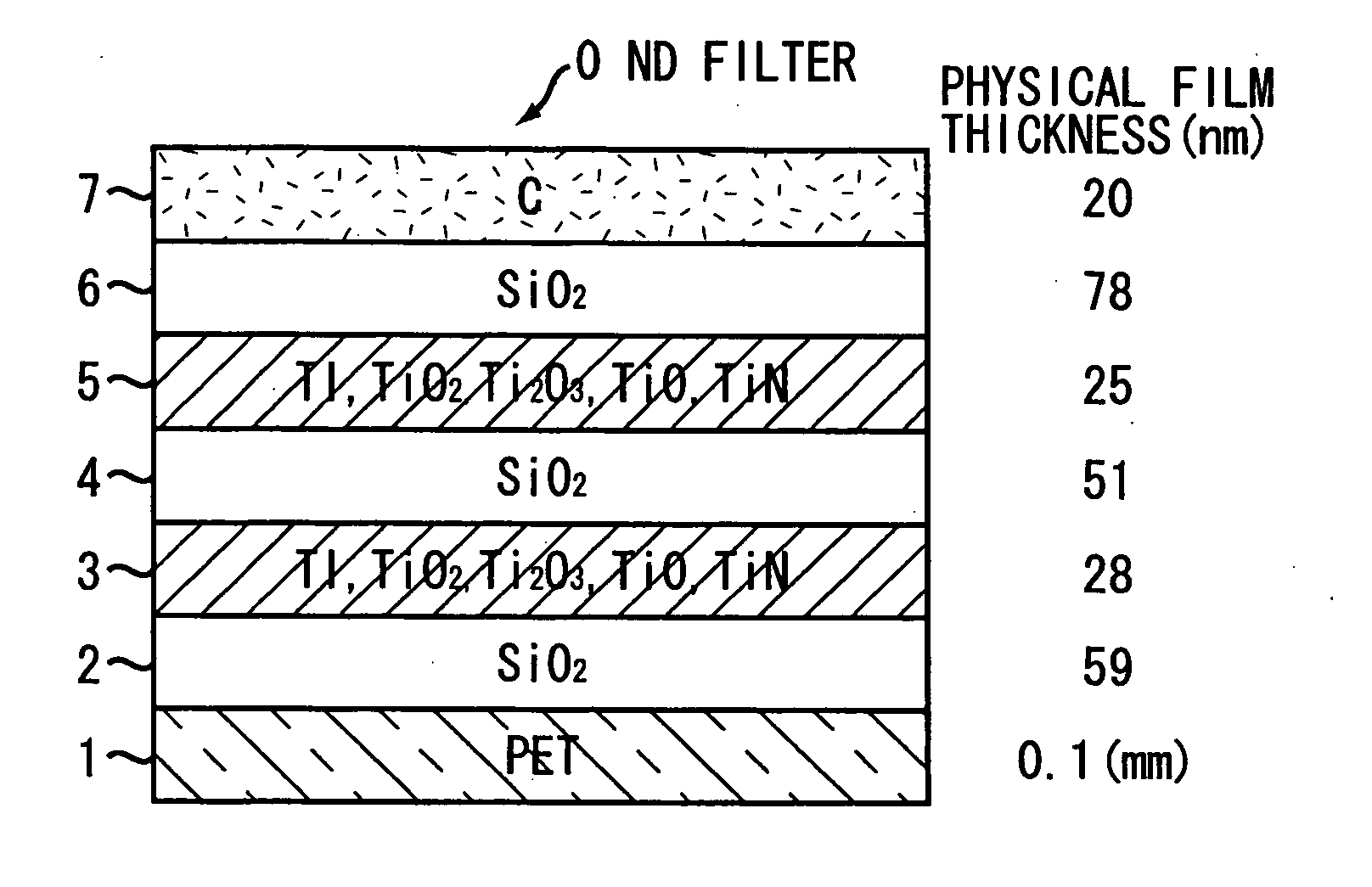
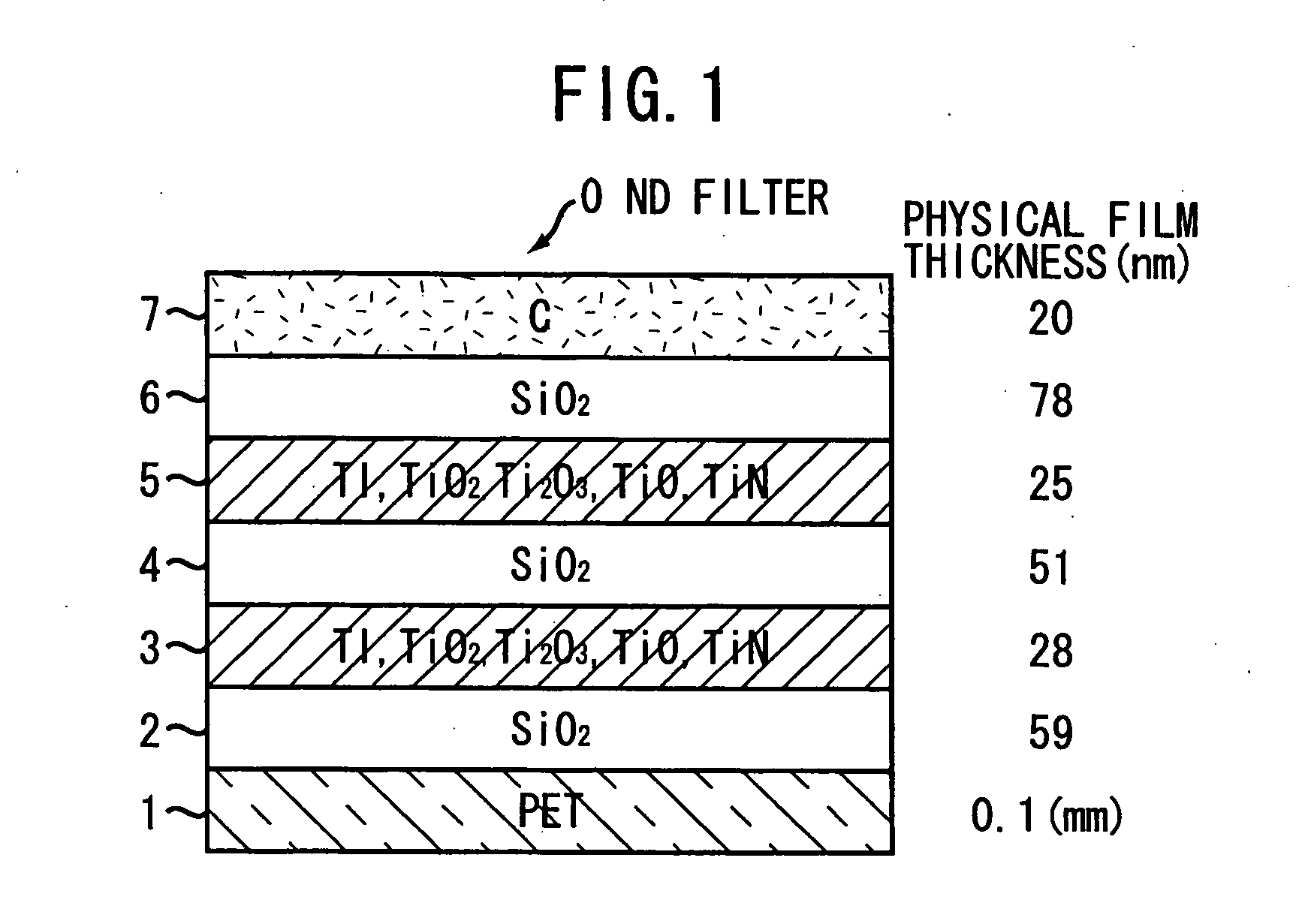
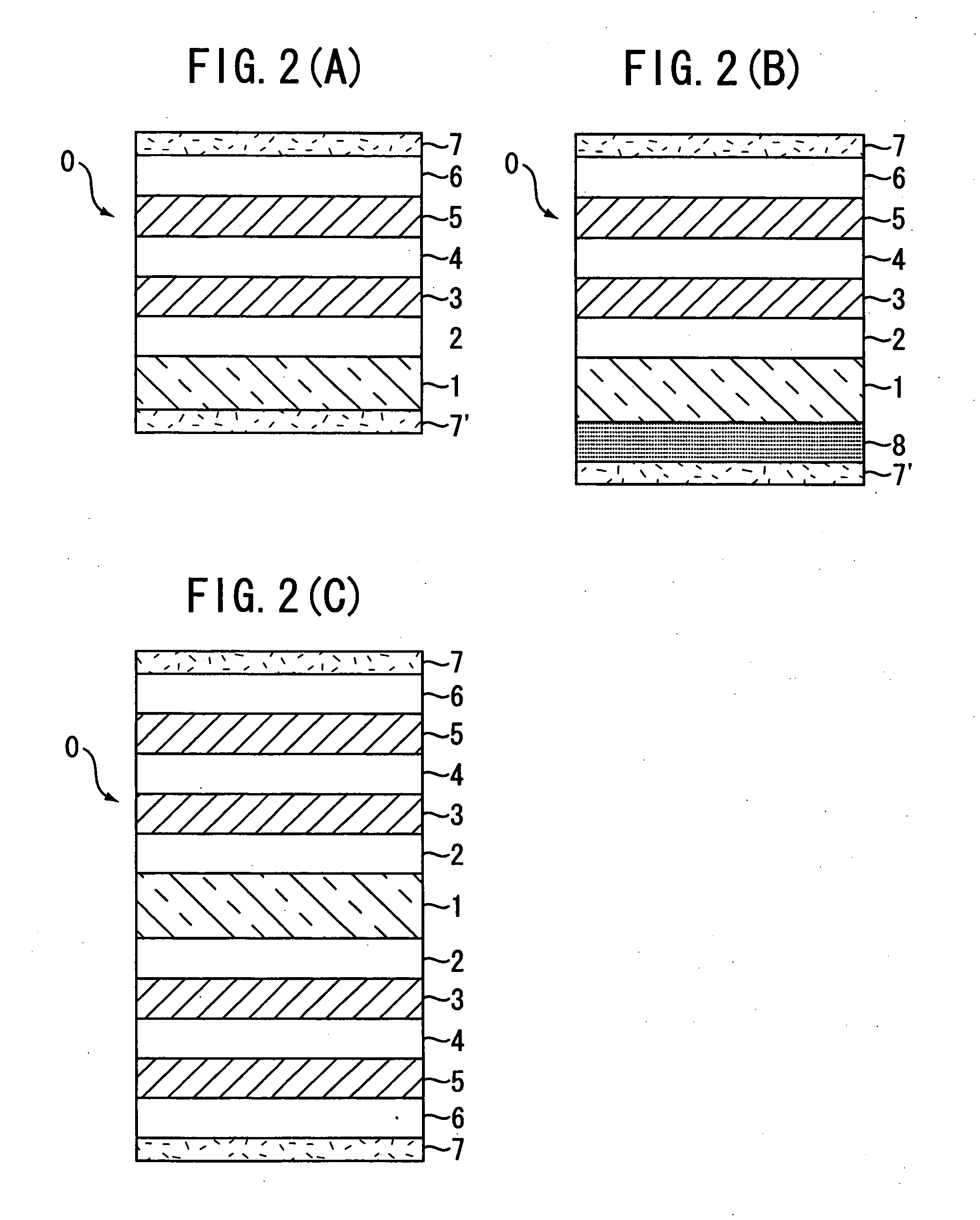
[0024] Embodiments of the present invention will be described in further detail with reference to the accompanying drawings. FIG. 1 is a schematic sectional view showing the configuration of a thin-film ND filter according to the present invention. As shown in FIG. 1, an ND filter 0 is a thin film type formed by laminating light-absorbing films 3 and 5 and dielectric films 2, 4, and 6 on a transparent substrate 1. Characteristically, a carbon film 7 is formed to clad the surface of the laminate. According to needs, it may be preferable to form another carbon film on the rear side of the transparent substrate 1. Preferably, the carbon film 7 is formed by the deposition process such as CVD or PVD at the deposition temperature of 150° C. or less. The light-absorbing films 3 and 5 are composed of a mixture of metal and compound thereof. For example, the metal material is Ti. Instead, it may be preferable to choose from Cr, Ni, NiCr, NiFe, or NiTi. The dielectric films 2, 4, and 6 are us...


PUM


Abstract

An ND filter is composed of a transparent substrate, a laminate of a light-absorbing film and a dielectric film formed on the transparent substrate, and a carbon film formed to clad a surface of the laminate of the light-absorbing films and the dielectric films. Depending on cases, another carbon film is also formed on a reverse side of the transparent substrate. The carbon film is formed by a deposition process at a deposition temperature ranging from a room temperature to 150° C. The light-absorbing film is formed of a mixture of metal and compound thereof, a material of the metal being selected from a group consisting of Ti, Cr, Ni, NiCr, NiFe, and NiTi. The dielectric film is formed of SiO2 or Al2O3.

Description

BACKGROUND OF THE INVENTION [0001] 1. Technical Field [0002] The present invention relates to an ND filter. The ND (neutral density) filter is used for stopping a part of incident light so as to decrease the amount of transmitting light uniformly over an entire visible range. [0003] 2. Related Art [0004] Generally, when the brightness of an object is too high for an imaging system such as a camera and a video, even if an aperture stop is minimized (namely, an aperture diameter is minimized), the aperture stop may still allow an excessive amount of incident light to enter into a light-sensitive surface. To solve this problem, it is a common practice to attach an ND filter to a part of the imaging system so as to limit the amount of light incident on the light-sensitive surface. In this case, the ND filter has flat spectral characteristics of simply decreasing the amount of incident light, and therefore needs to ensure uniform transmittance over an entire visible range of wavelength. ...

Claims


Application Information

Patent Timeline
IPC IPC(8): G02B27/00
CPCG02B5/205G03B11/04G03B9/02G03B11/00
Inventor KUNII, KOKI
Owner NIDEC COPAL CORPORATION
Why Eureka
Try Eureka