High efficiency switching power converter

a power converter and high efficiency technology, applied in the direction of efficient power electronics conversion, electric variable regulation, instruments, etc., can solve the problem of the practical limit of the maximum power rating of the flyback topology, and achieve the effect of high efficiency, cost-effectiveness and improved overall efficiency of such power converters

Inactive Publication Date: 2006-03-23
HUTCHINS PETER LAURENCE
View PDF13 Cites 13 Cited by
  • Summary
  • Abstract
  • Description
  • Claims
  • Application Information

AI Technical Summary

Benefits of technology

[0005] A cost effective solution to improve the overall efficiency of such power converters is described in which the power normally wasted in snubbers is scavenged and recycled by circuitry which delivers the majority of this energy to the secondary side load circuit. This is especially useful in high power, offline flyback converters where the high percentage of energy wasted in such snubber circuits places an effective practical limit on the maximum power ratings of the flyback topology. The invention is capable of multi-kilowatt power levels with high efficiency and low manufacturing costs.

Problems solved by technology

This is especially useful in high power, offline flyback converters where the high percentage of energy wasted in such snubber circuits places an effective practical limit on the maximum power ratings of the flyback topology.

Method used


Image

  • High efficiency switching power converter
  • High efficiency switching power converter
  • High efficiency switching power converter

Examples


Embodiment Construction

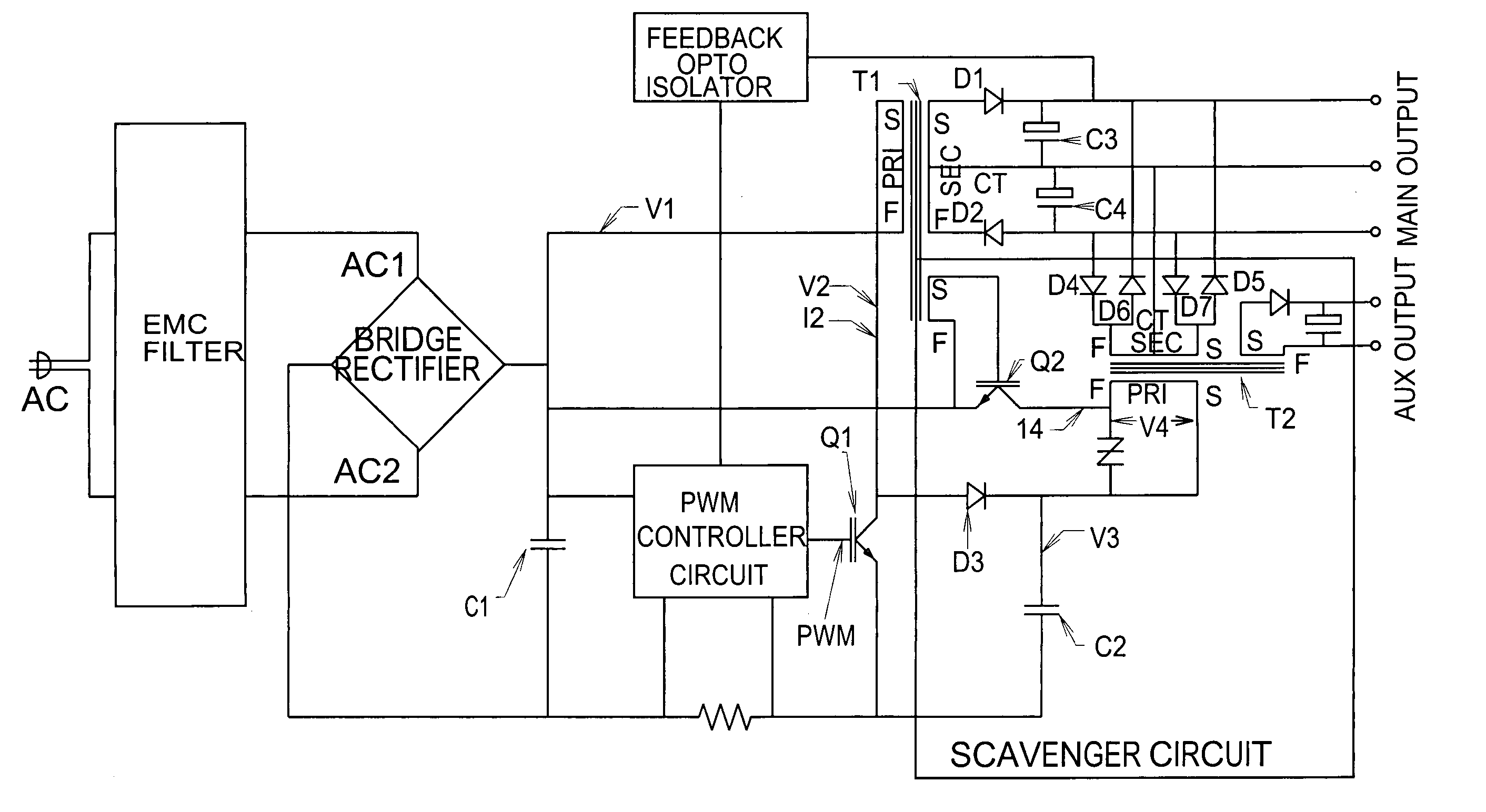
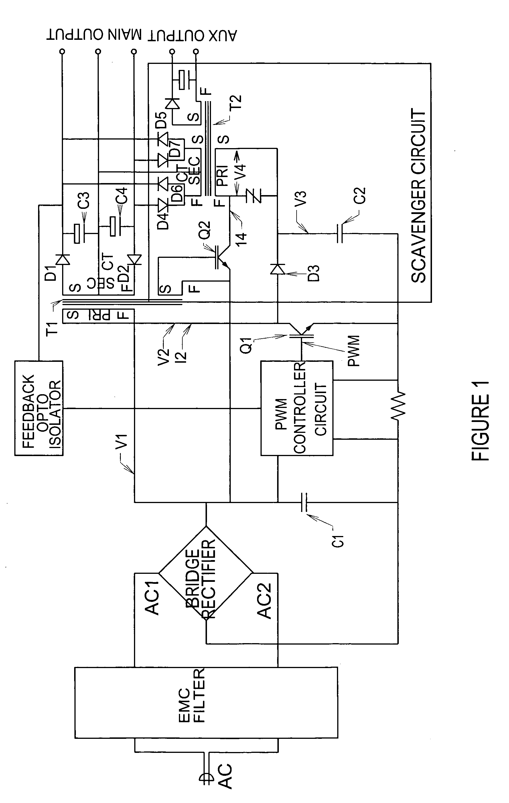
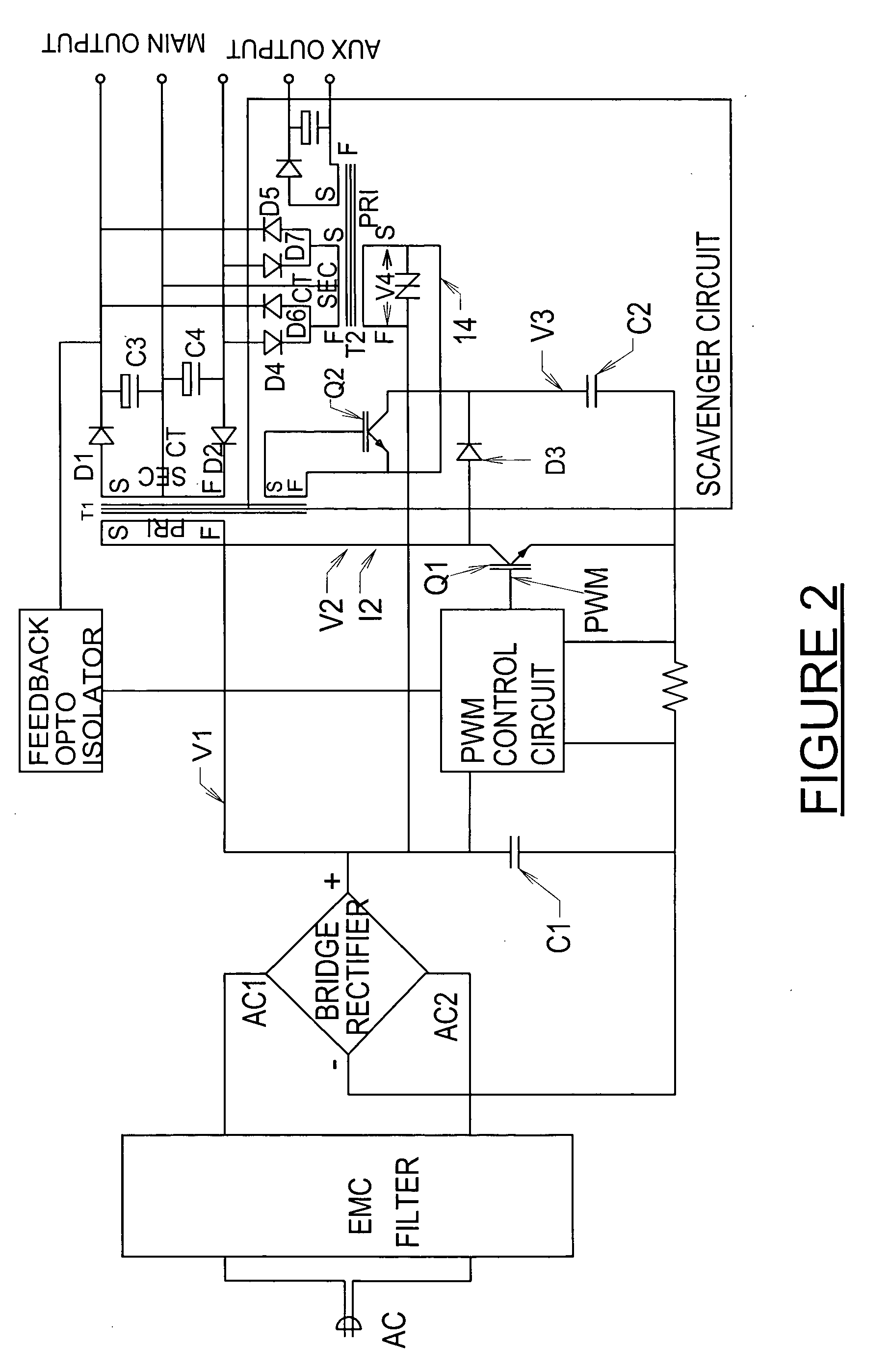
[0016] Referring to FIG. 1 it can be seen that a flyback converter stage is augmented with an efficiency boosting scavenger circuit comprising D3, C2, Q2, T2 and D4 thru D7. With reference to FIG. 3a the peak voltage acquired across C2 is the sum of [instantaneous rectified AC input voltage+T1 primary flyback voltage+voltage rise due to energy stored in stray inductance of T1 Primary]. FIGS. 3b, 3c and 3d show Q1 switching waveforms in expanded timebase and is typical of flyback operation in discontinuous mode. FIG. 3e shows the energy capturing action of D3 and C2, arranged also to prevent excessive voltage transients on Q1 due to T1 primary winding leakage inductance, current limiting is inherent in T1 flyback mode, so peak currents in Q2 and T2 are controlled to safe values.

[0017]FIGS. 3g and 3f show T2 primary current and voltage waveforms during scavenged energy transfer. Q2 is driven from a winding on T1 shown here with Q2 in ON-state during T1 flyback period, although this m...


PUM


Abstract

A high efficiency switching power converter has a flyback converter and a scavenger circuit to recycle the unavailable magnetic energy stored in the converter wiring and core leakage flux. Recycling this energy, which is normally dissipated in snubber networks, improves efficiency and considerably extends the feasible power levels of the flyback topology enabling high power output, low cost offline converters with low line current harmonics and active PFC.

Description

FIELD OF THE INVENTION [0001] The invention relates to electronic switching offline power converters.BACKGROUND OF THE INVENTION [0002] There is a global requirement for lower cost and more efficient electrical power converter design with active power factor correction. [0003] With the advent of regulations controlling Power Factor and line current harmonic levels of power converters connected to the AC mains supply, many higher power designs must include an additional active PFC correction stage at the front end, adding cost and further reducing the efficiency of the resulting multistage converter. [0004] A single stage offline flyback converter with PFC modulation can be devised however a significant amount of energy is unavoidably stored in stray circuit inductance both in the transformer and other high current conductors. This energy is not flux linked to the transformer secondary side output circuits, and if not controlled in some manner, causes destructive transient conditions...

Claims


Application Information

Patent Timeline
Patent Type & Authority Applications(United States)
IPC IPC(8): H02M3/335
CPCH02M1/34H02M1/4208Y02B70/1491H02M2001/342Y02B70/126H02M3/33576Y02B70/10H02M1/342
Inventor HUTCHINS, PETER LAURENCE
Owner HUTCHINS PETER LAURENCE
Why Eureka
Try Eureka