Transmission systems and methods

a transmission system and transmission technology, applied in the direction of mechanical equipment, transportation and packaging, gear transmissions with conventional variable ratios, etc., can solve the problems of compromising transmission load transfer design and coupling methods, affecting the operation of transmission load transfer, and increasing the difficulty of contact surface areas in changing the drive ratio. , to achieve the effect of increasing the flexibility of location

Inactive Publication Date: 2006-03-23
VOSS
View PDF37 Cites 70 Cited by
  • Summary
  • Abstract
  • Description
  • Claims
  • Application Information

AI Technical Summary

Benefits of technology

[0026] The invention's compactability and optimized construction allows for increased flexibility of location related to the system or vehicle framework. In specific regards to vehicle applicati

Problems solved by technology

Conventional variable ratio gear transmissions tend to be heavy and have high frictional losses.
Prior art transmission systems of this type have compromised transmission load transfer design and coupling methods to meet the demands of high force loads at low rotational speeds.
Transmission components with limited contact surface areas have increased difficulty in making changes in the drive ratio under high force loads.
In prior art, this reduction of the surface contact area to improve shift methods has resulted in the increased wear of the transmission components.
Prior art transmission carriers have limitations in the ability of the chain to engage the carrier elements that are at opposite ends of the carrier.
Transmission carriers that have the chain aligned across elements at opposite ends of each carrier results in an undesirable angle of the chain centerline in relation to the centerline of the connected elements.
Excessive crossover angles in prior art systems have resulted in high frictional losses and increased component wear.
The application of the transmission within the rear hub creates a separation in location from the initial drive force and limits the flexibility in location of the drive force transfer mechanisms.
The location of the prior art external transmissio

Method used


Image

  • Transmission systems and methods
  • Transmission systems and methods
  • Transmission systems and methods

Examples


Embodiment Construction

[0234] Referring now to the drawings for the purpose of illustrating a preferred embodiment of the present invention only, and not for purposes of limiting the same:

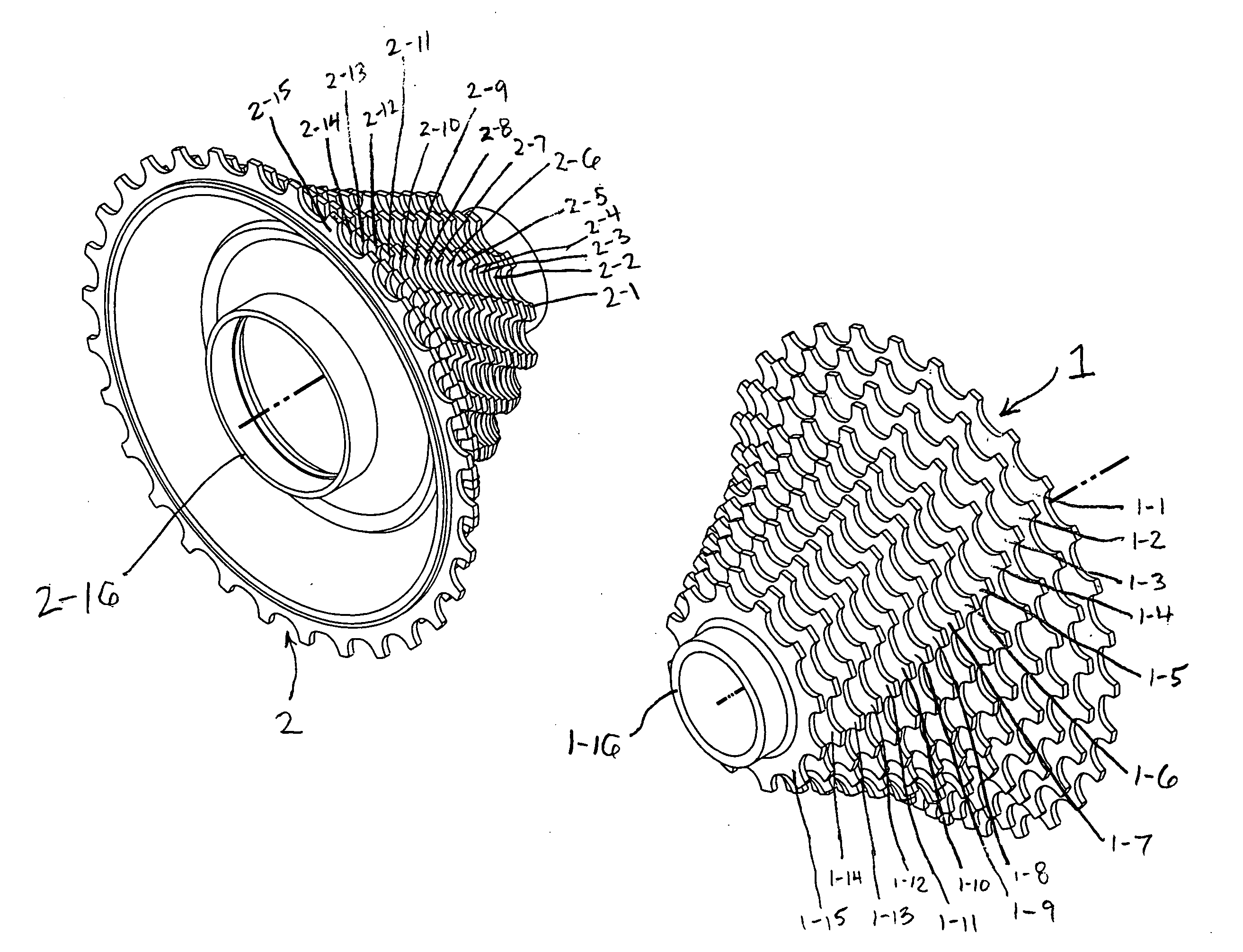
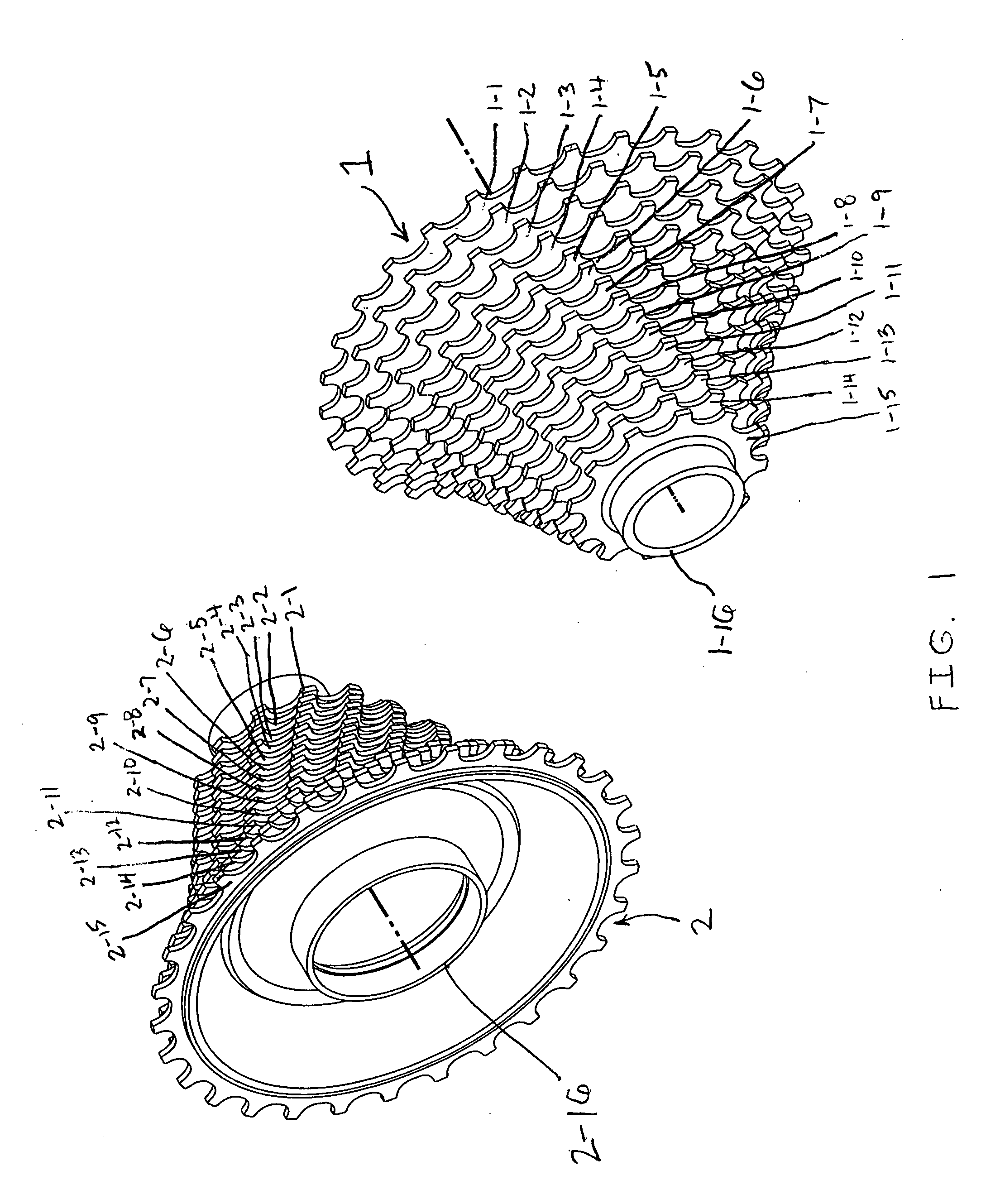
[0235]FIG. 1 is an embodiment of a transmission carrier 1 having a plurality of fixed and coaxial ratioed drive elements of decreasing diameters located essentially parallel to a transmission carrier 2 having a plurality of fixed coaxial driven elements of decreasing diameters facing the opposite direction of transmission carrier 1. Transmission drive carrier 1 has fixed drive elements 1-1, 1-2, 1-3, 1-4, 1-5, 1-6, 1-7, 1-8, 1-9, 1-10, 1-11, 1-12, 1-13, 1-14, and 1-15 and each evenly spaced drive element is a smaller diameter in order from fixed drive element 1-1 through 1-15. Transmission drive carrier 1 has an inner diameter hub 1-16 and is fixable to an axle for rotation of the carrier around the carrier's central axis. Transmission carrier 2 has fixed driven elements 2-1, 2-2, 2-3, 2-4, 2-5, 2-6, 2-7, 2-8, 2-9, 2-10...


PUM


Abstract

A transmission includes a pair of conical transmission element carriers with one being a drive carrier and one being a driven carrier. The drive carrier has a plurality of fixed drive elements attached. The driven carrier has a plurality of fixed driven elements attached. An endless connecting element rotationally couples a drive carrier element to a driven carrier element to provide a transmission output ratio. Also, a shift element means transfers the endless connecting element between a selected drive element to a corresponding driven element to establish a change in the rotational ratio between the drive carrier and the driven carrier.

Description

REFERENCE TO RELATED APPLICATIONS [0001] The present application claims the priority of provisional application No. 60 / 610,944 filed Sep. 20, 2004 entitled BICYCLE SYSTEMS AND METHOD. [0002] The present application is related to pending application Ser. No. 10 / 113,931, filed Apr. 2, 2002 entitled VEHICLES AND METHODS USING CENTER OF GRAVITY AND MASS SHIFT CONTROL SYSTEM and to provisional application No. 60 / 622,846 filed Oct. 29, 2004 entitled METHODS FOR MANUFACTURING A GEAR and RESULTING GEAR PRODUCTS. [0003] The present application is also related to an application filed Sep. 19, 2005 by the same inventor entitled IMPROVED VEHICLE SYSTEMS AND METHOD.BACKGROUND OF THE INVENTION [0004] 1. Field of the Invention [0005] This invention generally relates to transmission systems and methods. The present invention relates to transmission systems and methods with a particular emphasis on systems involving high efficiency, low frictional loss, and / or torque loads at low revolutions per min...

Claims


Application Information

Patent Timeline
IPC IPC(8): F16H59/00F16H61/00B62M9/123B62M9/10B62M9/124B62M9/128B62M9/134B62M9/138
CPCB62M9/10F16H9/24B62M9/105
Inventor VOSS, DARRELL
Owner VOSS
Why Eureka
Try Eureka