Periodic patterns and technique to control misalignment between two layers

a technology of two layers and periodic patterns, applied in the field of metalrology systems, can solve the problems of limited optical microscope accuracy, reworked or discarded semiconductor wafers, and malfunction of electronic devices fabricated, and achieve the effects of high sensitivity, high linearity, and high sensitivity

Inactive Publication Date: 2006-03-30
ABDULHALIM IBRAHIM +3
View PDF99 Cites 43 Cited by
  • Summary
  • Abstract
  • Description
  • Claims
  • Application Information

AI Technical Summary

Benefits of technology

[0008] An advantage of the target is the use of the same diffraction system and the same target to measure critical dimension and overlay misregistration. Another advantage of the measurement of misregistration of the target is that it is free from optical asymmetries usually associated with imaging.
[0011] In one embodiment, a neutral polarization angle, defined as an incident polarization angle where the differential intensity is equal to zero for all overlay misregistrations, is determined. The slope of differential intensity as a function of incident polarization angle is highly linear when plotted against the overlay misregistration. This linear behavior reduces the number of parameters that need to be determined and decreases the polarization scanning needed. Thus, the method of detecting misalignment is faster when using the slope measurement technique.

Problems solved by technology

If the two overlay targets are misaligned relative to each other, then the electronic devices fabricated will malfunction, and the semiconductor wafer will need to be reworked or discarded.
The accuracy of the optical microscope is limited by the accuracy of the line profiles in the target, by aberrations in the illumination and imaging optics and by the image sampling in the camera.
Such methods are complex and they require full imaging optics.
These techniques suffer from a number of drawbacks.
First, the grabbed target image is highly sensitive to the optical quality of the system, which is never ideal.
The optical quality of the system may produce errors in the calculation of the overlay misregistration.
Second, optical imaging has a fundamental limit on resolution, which affects the accuracy of the measurement.
Third, an optical microscope is a relatively bulky system.
It is difficult to integrate an optical microscope into another system, such as the end of the track of a lithographic stepper system.

Method used


Image

  • Periodic patterns and technique to control misalignment between two layers
  • Periodic patterns and technique to control misalignment between two layers
  • Periodic patterns and technique to control misalignment between two layers

Examples


Embodiment Construction

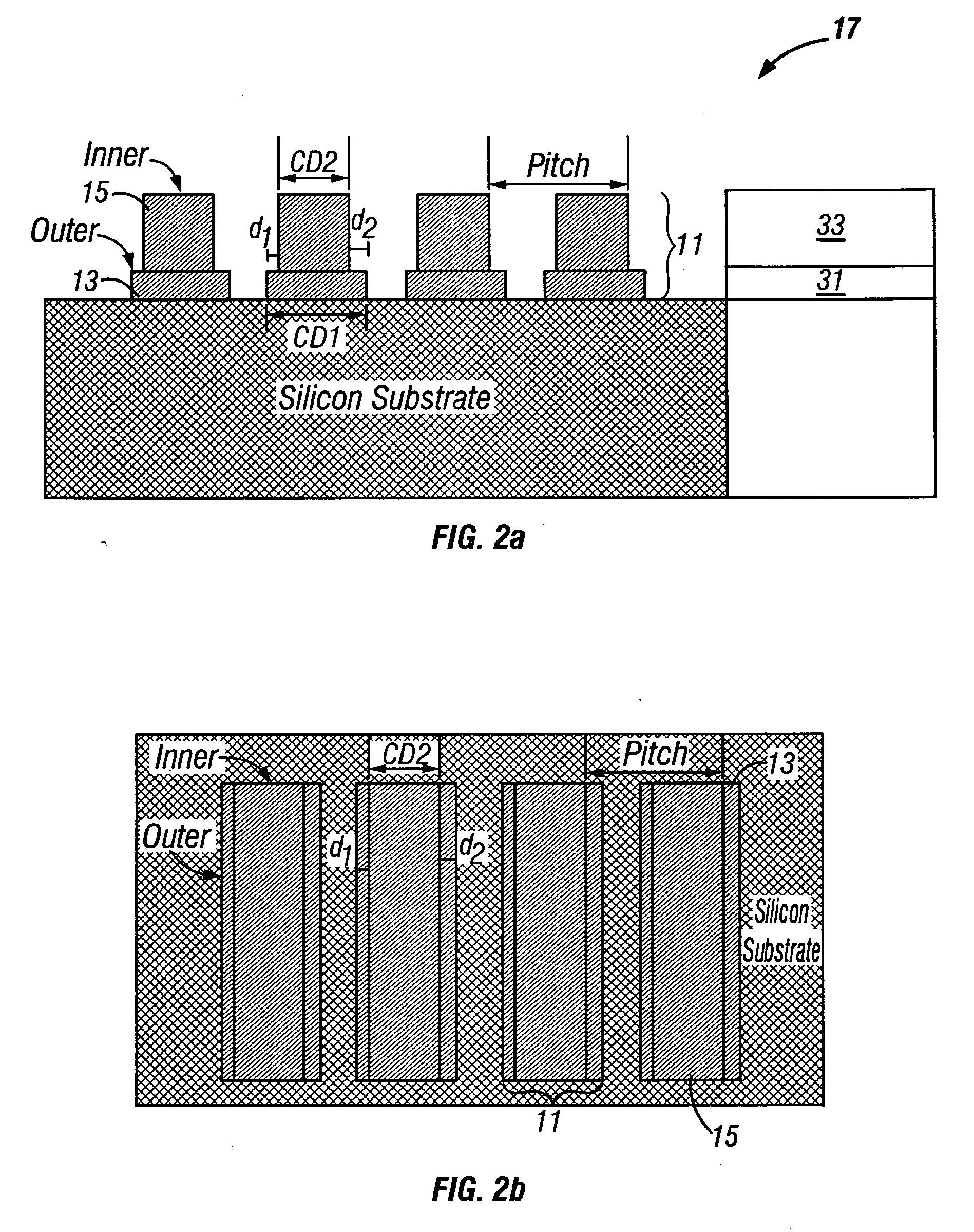
[0028]FIG. 2a is a cross-sectional view of a target 11 comprising two periodic structures 13, 15 on two layers 31, 33 of a device 17. The second periodic structure 15 is overlying or interlaced with the first periodic structure 13. The layers and the periodic structures may be at the same or different heights. The device 17 can be any device of which the alignment between two layers, particularly layers having small features on structures, needs to be determined. These devices are typically semiconductor devices; thin films for magnetic heads for data storage devices such as tape recorders; and flat panel displays.

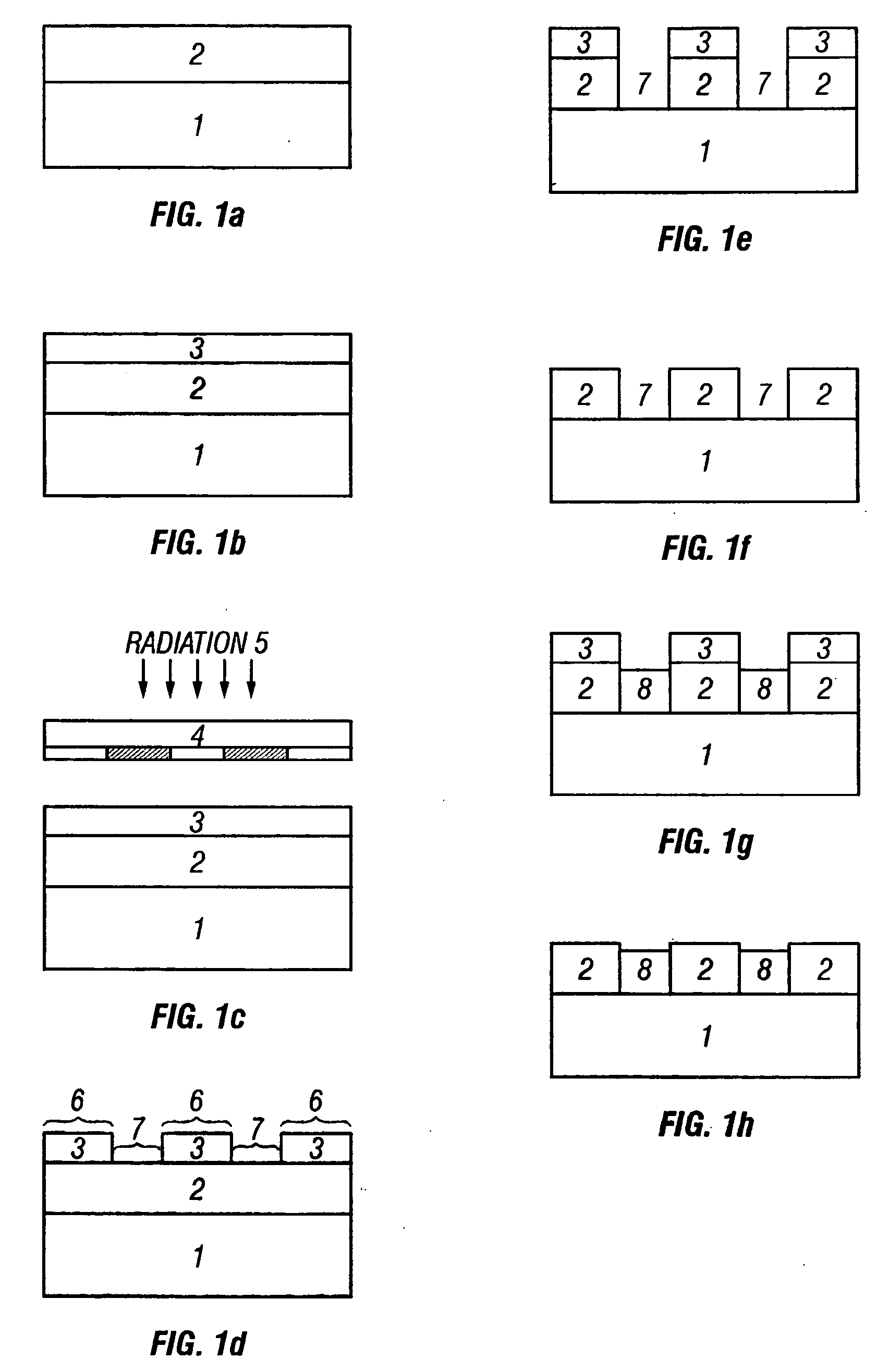
[0029] As shown in FIGS. 1a-1h, a device 17 is generally formed in a basic series of steps for each layer. First, as shown in FIG. 1a, a layer 2 is formed on a semiconductor substrate 1. The layer 2 may be formed by oxidization, diffusion, implantation, evaporation, or deposition. Second, as shown in FIG. 1b, resist 3 is deposited on the layer 2. Third, as shown in FIG. 1...


PUM

PropertyMeasurementUnit
diffracted intensityaaaaaaaaaa

Abstract

A method and system to measure misalignment error between two overlying or interlaced periodic structures are proposed. The overlying or interlaced periodic structures are illuminated by incident radiation, and the diffracted radiation of the incident radiation by the overlying or interlaced periodic structures are detected to provide an output signal. The misalignment between the overlying or interlaced periodic structures may then be determined from the output signal.

Description

CROSS-REFERENCE TO RELATED APPLICATIONS [0001] This application is a continuation of application Ser. No. 10 / 699,153, filed Oct. 30, 2003; which application is a continuation of application Ser. No. 09 / 833,084 filed Apr. 10, 2001, now abandoned; which applications are incorporated by reference as if fully set forth herein. This application is also related to application Ser. No. 10 / 682,544, filed Oct. 8, 2003.BACKGROUND OF THE INVENTION [0002] The invention relates in general to metrology systems for measuring periodic structures such as overlay targets, and, in particular, to a metrology system employing diffracted light for detecting misalignment of such structures. [0003] Overlay error measurement requires specially designed marks to be strategicaily placed at various locations, normally in the scribe line area between dies, on the wafers for each process. The alignment of the two overlay targets from two consecutive processes is measured for a number of locations on the wafer, a...

Claims


Application Information

Patent Timeline
Patent Type & Authority Applications(United States)
IPC IPC(8): H01L21/306G01L21/30G01B11/00G03F7/20G03F9/00H01L21/027H01L23/544
CPCG03F7/70633H01L22/12H01L23/544H01L2223/54453H01L2924/0002G01B11/14H01L2924/00G01B11/26G01N21/9501H01L2223/54426H01L2223/5446
Inventor ABDULHALIM, IBRAHIMADEL, MIKEFRIEDMANN, MICHAELFAEYRMAN, MICHAEL
Owner ABDULHALIM IBRAHIM
Why Eureka
Try Eureka