Magnetic head assembly and magnetic disc device

a magnetic disc and head assembly technology, applied in the direction of maintaining head carrier alignment, recording information storage, instruments, etc., can solve the problems of increasing the use of magnetic disk drives in more severe environments, difficult writing, and disabled writing operations

Inactive Publication Date: 2006-03-30
PANASONIC CORP
View PDF18 Cites 20 Cited by
  • Summary
  • Abstract
  • Description
  • Claims
  • Application Information

AI Technical Summary

Benefits of technology

[0027] As described above, according to the magnetic disk drive and magnetic head assembly of the present invention, stable magnetic reading and writing is possible under a wider range of temperature environmental conditions compared with prior art, and magnetic disk drives, which can be used even under environments where the use of magnetic devices was conventionally difficult, can be implemented.

Problems solved by technology

On the other hand, if the temperature is lower than the guaranteed range, the coercivity of the magnetic disk 2 increases, which makes writing difficult even if the reading of information is without problems, so the writing operation is disabled until the temperature of the magnetic disk drive becomes higher than the predetermined temperature by the heater of the vehicle main body (e.g. see Masahiko Takizawa and other: “Application of HDD to navigation”, Pioneer Technical Information Magazine, 2002, Vol. 12, No. 1 [Online] [searched on Oct. 1, 2002], Internet ).
However now applications which are different from conventional usage are already emerging, such as installing a magnetic disk drive in a car navigation system, and it is expected that using magnetic disk drives under more severe environments will increase.
For example, under extremely low temperatures below −20° C., or at high temperatures exceeding 70° C., conventional magnetic disk drives have problems of reliability of magnetic recording because of the temperature dependency of the coercivity of the magnetic disk 2, and there is the problem of reliability of the magnetic disk drive in terms of the stability of the flying height of the magnetic head slider.
If a double structured outer shell is used to make the external environment and internal environment independent from each other, the size and weight of the magnetic disk drive itself increases, which is not appropriate for an application where portability is important.
This large change of flying height from the inner periphery to the outer periphery is not desirable in terms of both the reliability and efficiency of magnetic reading / writing and the reliability of the magnetic disk drive.
In other words, if the flying height changes considerably from the inner periphery to the outer periphery, the spacing loss factor of the magnetic reading / writing caused by flying cannot be uniform between the inner periphery and outer periphery, and the efficiency of the magnetic reading / writing deteriorates at a position of the inner periphery or outer periphery where the flying height increases.
In terms of the reliability of the magnetic disk drive, the flying height decreases at the outer periphery at low temperatures, and the flying height decreases at the inner periphery at high temperatures, so the contact of the magnetic head slider 1 and the magnetic disk 2 is a concern at both low temperatures and high temperatures, and optimization for the reliability of the magnetic disk drive is required for both low temperatures and high temperatures, which makes optimization of the magnetic disk drive difficult.

Method used


Image

  • Magnetic head assembly and magnetic disc device
  • Magnetic head assembly and magnetic disc device
  • Magnetic head assembly and magnetic disc device

Examples


embodiment 1

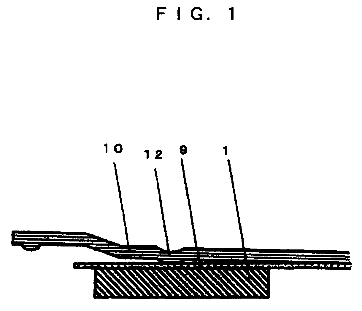
[0050]FIG. 1 is a diagram depicting the configuration of the magnetic head assembly 3 according to the first embodiment of the present invention. In FIG. 1, the magnetic head slider 1 is adhered to the plate spring 9 which is a flexure thin plate, and the plate spring 9 contacts the load beam 10 via the dimple 12. The external size of the magnetic head slider 1 is about 1.2 mm×1.0 mm and the height is about 0.3 mm. The material of the magnetic head slider 1 is alumina carbide titanate, and the thermal expansion coefficient of alumina carbide titanate is 7.8×10⁻⁶ / ° C. The plate spring 9, which is a flexure thin plate, is made of a 36Ni—Fe alloy which is an alloy of nickel and iron. The thermal expansion coefficient of this alloy is 1.2×10⁻⁶ / ° C.

[0051] The operation and function of the magnetic head assembly 3 constructed as above will now be described with reference to FIG. 2-FIG. 11.

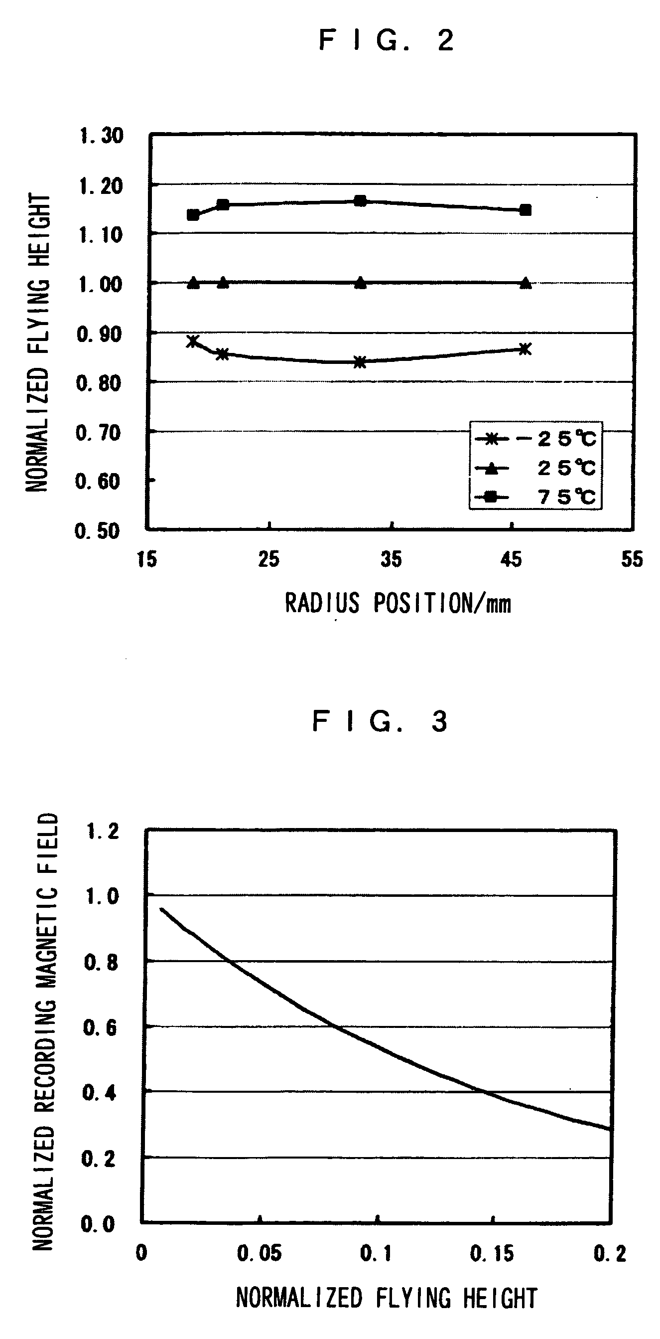
[0052]FIG. 2 shows the flying height of the magnetic head slider 1 with the configuration of the ma...

embodiment 2

[0086]FIG. 12 is a diagram depicting the configuration of the magnetic head assembly 3 according to the second embodiment of the present invention. In FIG. 12, a thin film 7 is formed on the rear face of the sliding surface for the magnetic disk 2 of the magnetic head slider 1, and the magnetic head slider 1 is adhered to the plate spring 9 which is a flexure thin plate via this thin film 7. The plate spring 9 contacts the load beam 10 via the dimple 12. The external size of the magnetic head slider 1 is about 1.2 mm×1.0 mm and the height is about 0.3 mm. The material of the magnetic head slider 1 is alumina carbide titanate, and for the thin film 7, a 36Ni—Fe alloy, which is an alloy of nickel and iron, is used. The thermal expansion coefficient of alumina carbide titanate is 7.8×10⁻⁶ / ° C., and the thermal expansion coefficient of the 36Ni—Fe alloy is 1.2×10⁻⁶ / ° C.

[0087]FIG. 13 shows the relationship between the rate of change of the crown and the film thickness t of the thin film...

embodiment 3

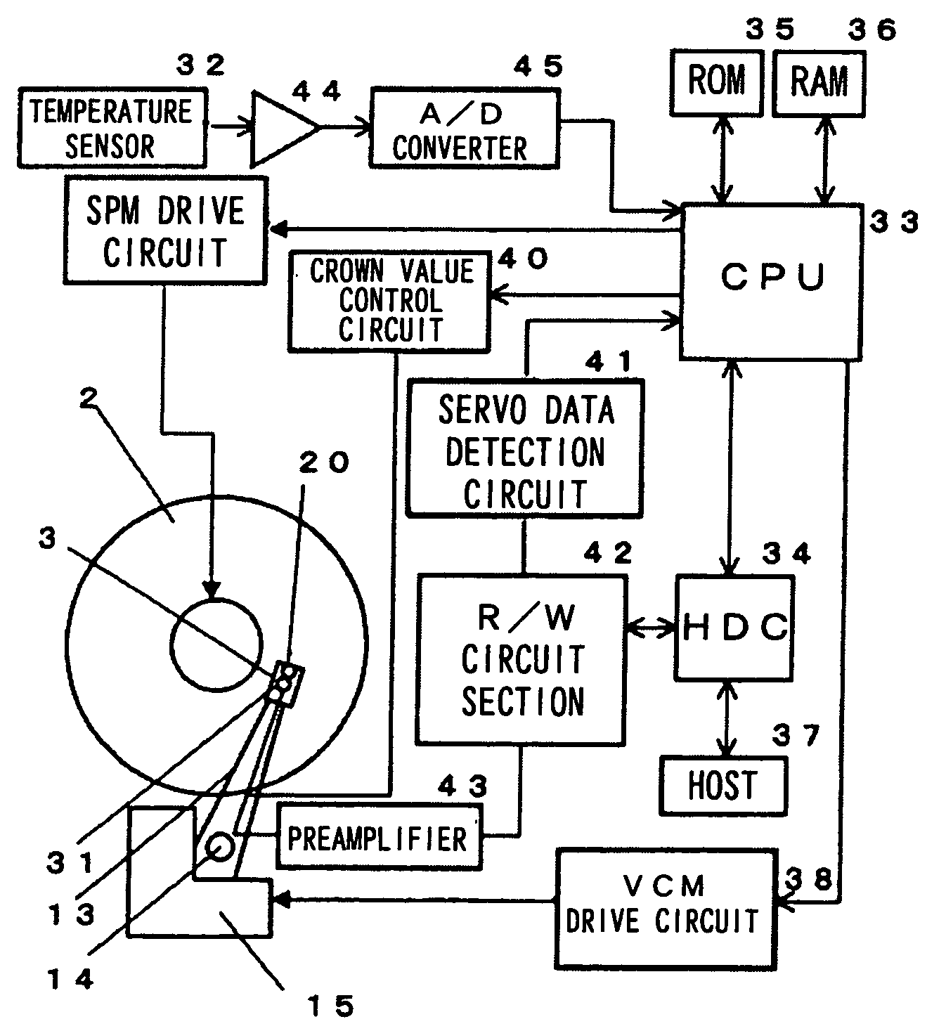
[0090]FIG. 15 is a block diagram depicting the configuration of the magnetic disk drive according to the third embodiment of the present invention.

[0091] In FIG. 15, the magnetic head assembly 3 comprises a magnetic head slider 1 on which a magnetic read / write element 20 for reading and writing information is mounted, a suspension 4 which further comprises a plate spring 9, a flexible circuit 8 and a load beam 10, and a piezoelectric element 31 which functions as the flying height control means. The read / write circuit section 42 comprises circuits which generate write signals, generate read information from the read signals amplified by the preamplifier 43, and modulate / demodulate the read / write signals, and the actuator mechanism 13 comprises an arm which supports the magnetic head assembly 3 and a drive mechanism for rotating this arm around a bearing 14 within a predetermined angle range, that is a voice coil motor 15. 38 is a voice coil motor drive circuit for driving the actua...


PUM

PropertyMeasurementUnit
temperatureaaaaaaaaaa
operating temperatureaaaaaaaaaa
temperatureaaaaaaaaaa

Abstract

The present invention implements a magnetic disk drive usable under a wide range of temperature environment conditions, and a magnetic head assembly. The flying height of a magnetic head slider (1) can be controlled against a change of temperature so that the flying height of the magnetic head slider (1) is low at low temperatures and high at high temperatures, thereby the variations of the coercivity of a magnetic disk (2) can be cancelled. Further, by setting the rate of change of the crown value with respect to the change of temperature to 0.26 to 0.62 nm/° C., the flying height can be controlled so that the flying height becomes low at low temperatures and high at high temperatures, while maintaining the uniformity of the profile of the flying height of the magnetic head slider (1) from the inner periphery to the outer periphery of the magnetic disk (2).

Description

TECHNICAL FIELD [0001] The present invention relates to a magnetic disk drive for writing to and reading from a magnetic disk using a magnetic read / write element on a magnetic head slider by operating an actuator mechanism having a magnetic head assembly at the tip while rotating the magnetic disk and moving a position of the magnetic head slider with respect to the magnetic disk, and relates to a magnetic head assembly which is used in this magnetic disk drive and comprises a head slider and a suspension. BACKGROUND ART [0002] Generally, as shown in FIG. 16, a magnetic disk drive is provided with a magnetic head assembly 3, which further comprises a magnetic head slider 1 and a suspension, a magnetic disk 2, magnetic disk rotation drive means 16, such as a spindle motor, and an actuator mechanism 13 (including a bearing 14 and voice coil motor) for moving the magnetic head assembly 3 along the information recording surface of the magnetic disk 2, which are housed in a body 17 made ...

Claims


Application Information

Patent Timeline
Patent Type & Authority Applications(United States)
IPC IPC(8): G11B21/02G11B19/02G11B21/24G11B33/14G11B5/60G11B21/21G11B25/04
CPCG11B21/21G11B5/6005G11B5/6064G11B5/6082
Inventor TAKAGI, SUSUMUMIZOH, YOSHIAKI
Owner PANASONIC CORP
Why Eureka
Try Eureka