Apparatus having and method for implementing a distributed architecture for receiving and/or transmitting radio frequency signals

a radio frequency signal and distributed architecture technology, applied in the field of apparatus having and method for implementing a distributed architecture for receiving and/or transmitting radio frequency signals, can solve the problems of high-quality and relatively expensive cables, increase the cost, complexity, and simplify and reduce the cost and weight of the system. , to achieve the effect of improving the sensitivity of the rf section and simplifying the system

Active Publication Date: 2006-03-30
PANASONIC AUTOMOTIVE SYST OF AMERICA
View PDF10 Cites 23 Cited by
  • Summary
  • Abstract
  • Description
  • Claims
  • Application Information

AI Technical Summary

Benefits of technology

[0013] An advantage of the present invention is that the RF front ends are distributed away from the electrically-noisy environment of the multi-service device to positions proximate their corresponding antenna thereby preserving if not improving the sensitivity of the RF sections.
[0014] A further advantage of the present invention is that the RF front ends are connected to their corresponding demodulators / channel decoders by a single cable, thereby simplifying and reducing the cost and weight of the system.
[0015] A still further advantage of the present invention is that by distributing the RF front ends to positions proximate the antennas additional space is made available within the multi-service device.

Problems solved by technology

Generally, each of those separate RF front ends must be interconnected with a corresponding antenna by high-quality and relatively expensive cables.
Such small-magnitude signals are susceptible to degradation from conductive electrical noise and radiation interference.
This need to use several high-quality cables to interconnect the multi-service device to its antennas increases the cost, complexity, and weight of the system.
An electrically noisy environment is thereby created which may undesirably impact the sensitivity of the RF front ends and may degrade the quality of the received signal.
Further, since the single housing must accommodate the several processing platforms and associated circuitry, space within the housing is at a premium and the process of adding enhanced features, additional functions, or expanding the processing capability of the multi-service device is somewhat more complex than it otherwise might be.

Method used


Image

  • Apparatus having and method for implementing a distributed architecture for receiving and/or transmitting radio frequency signals
  • Apparatus having and method for implementing a distributed architecture for receiving and/or transmitting radio frequency signals
  • Apparatus having and method for implementing a distributed architecture for receiving and/or transmitting radio frequency signals

Examples


first embodiment

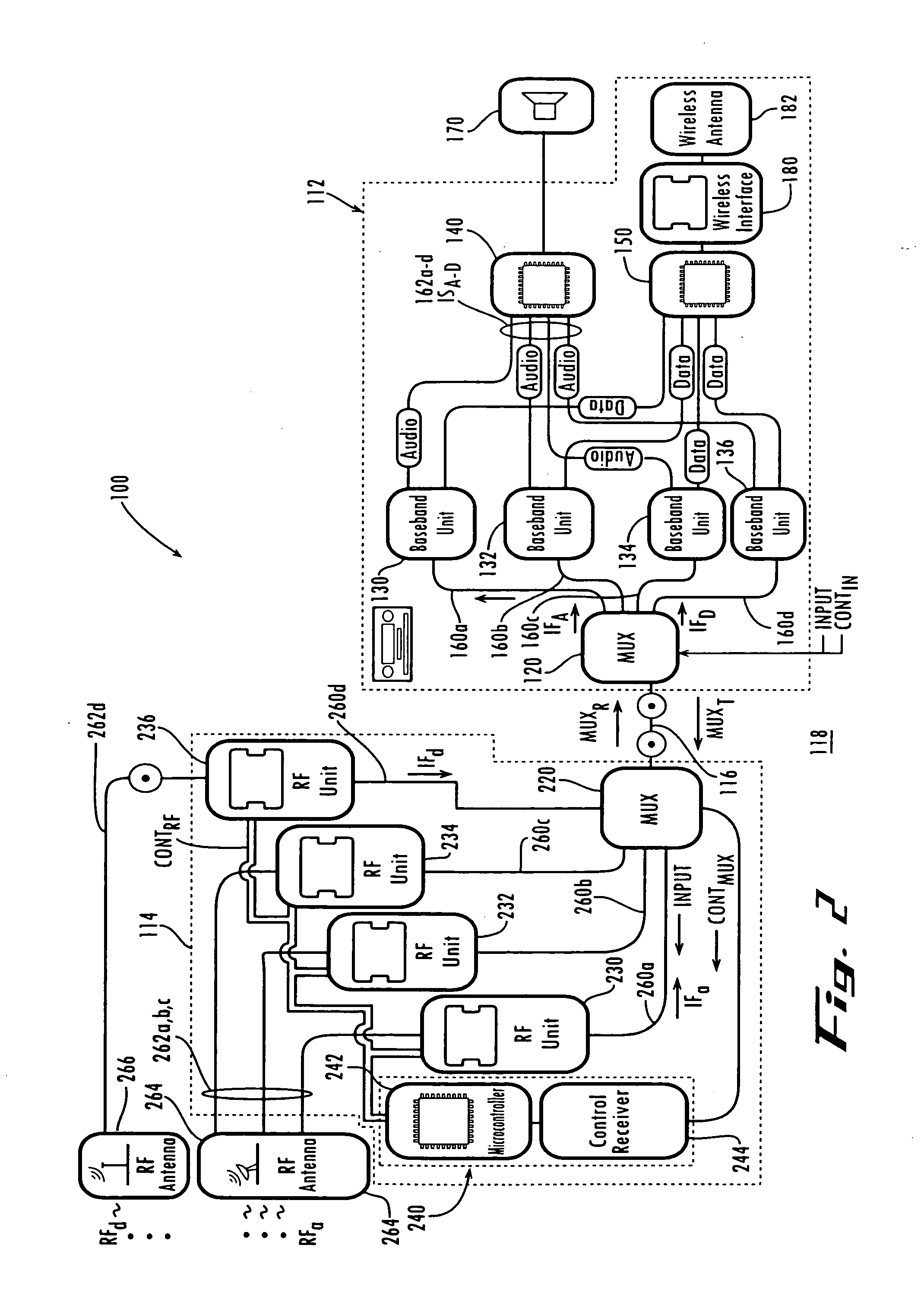
[0030] Conversely, the present invention reduces the need for multiple RF sections, multiple information and / or control / data lines, and multiple antenna cables by utilizing an improved distributed architecture. More particularly, and with reference to FIG. 2, a system 100 having a distributed architecture for receiving and / or transmitting radio frequency signals is schematically shown. System 100 includes head unit 112, transceiver unit 114 and multiplexed link 116. System 100 is, in this exemplary embodiment, installed in vehicle 118, such as, for example, an automobile.

[0031] Head unit 112 is generally similar to head unit 12 in that it also includes various functional units or circuits, such as, for example, audio control and processing circuitry such as volume, tone and fade / balance control circuitry, input source selection circuitry and other control circuitry. Head unit 112 is also typically installed in a vehicle, such as, for example, an automobile, although it is to be unde...

second embodiment

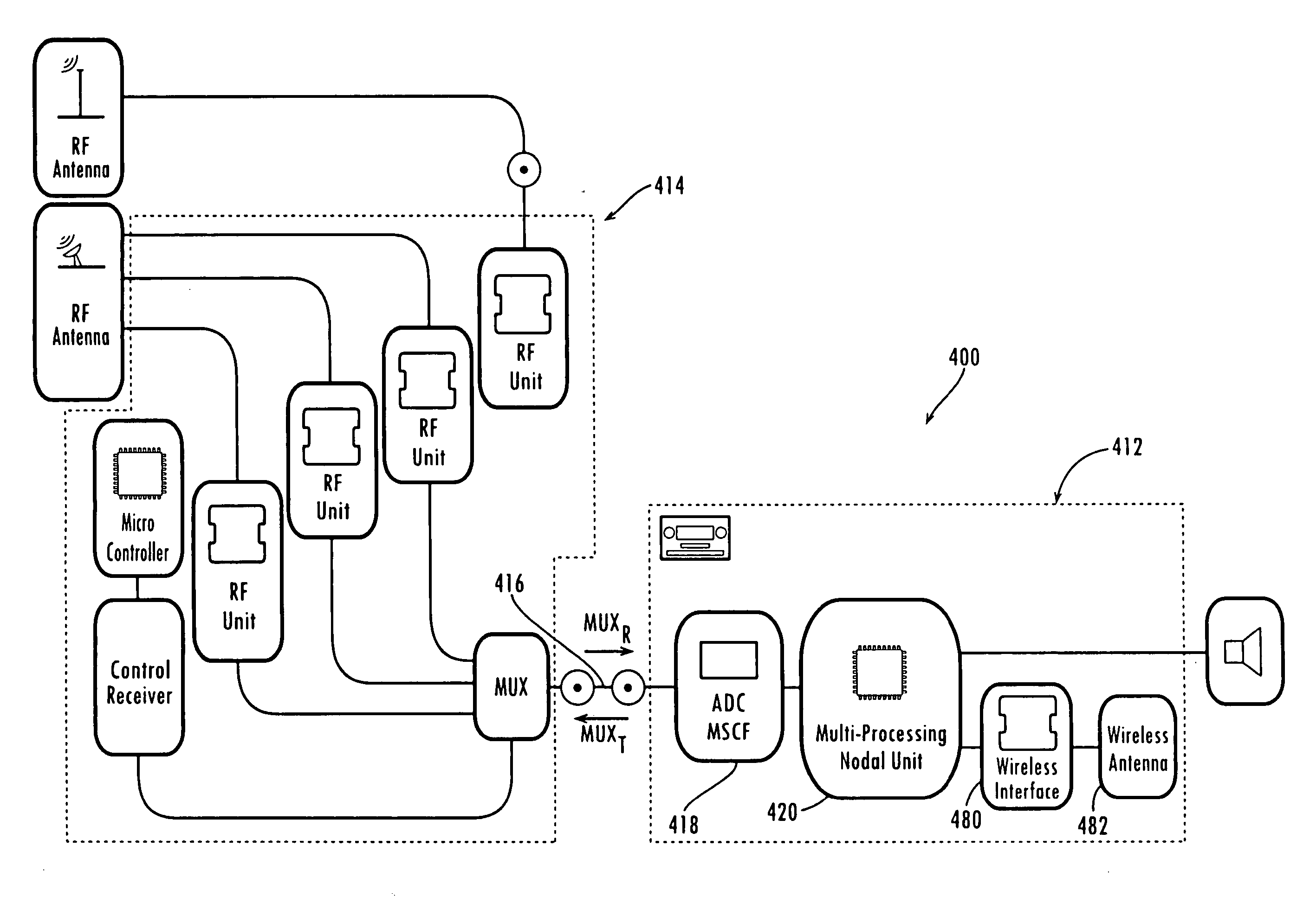
[0053] Referring now to FIG. 4, there is shown a schematic diagram of a system 400 having a distributed architecture for receiving and / or transmitting radio frequency signals. System 400 includes head unit 412, receiving unit 414 and multiplexed link 416. Receiving unit 414 and multiplexed link 416 are substantially similar to transceiver unit 114 and multiplexed link 116 described above in connection with system 100, and therefore only head unit 412 is discussed in detail hereinafter.

[0054] Head unit 412 includes analog-to-digital conversion and filtering stage (ADCFS) 418 and multi-processing nodal unit 420. Generally, head unit 412 receives from receiver unit 414 via multiplexed link 416 a multiplexed down-converted intermediate frequency (IF) signal that combines into one signal the several radio frequency signals received from the multiple broadcast services that system 400 is configured to receive.

[0055] ADCFS 418 includes circuitry (not shown) for performing a conventional a...


PUM


Abstract

A distributed architecture system for receiving radio frequency (RF) signals includes a receiving unit receiving a plurality of RF signals. The receiving unit includes means for combining the plurality of RF signals into a multiplexed signal. A head unit receives and separates the multiplexed signal into a plurality of information signals. The head unit prepares the information signals for presentation to a user. The head unit is disposed remotely from the receiving unit. A multiplexed link carries the multiplexed signal from the receiving unit to the head unit.

Description

CROSS-REFERENCE TO RELATED APPLICATIONS [0001] This application claims the benefit of U.S. Provisional Patent Application Ser. No. 60 / 611,398, filed 20 Sep. 2004 and entitled RADIO ARCHITECTURE UTILIZING IF I / Q OUTPUT SEPARATION, and of U.S. Provisional Patent Application Ser. No. 60 / 611,317, filed 20 Sep. 2004 and entitled IF MULTIPLEXED RADIO ARCHITECTURE FOR AUTOMOTIVE ENTERTAINMENT EQUIPMENT.FIELD OF THE INVENTION [0002] The present invention relates generally to an apparatus having and method for implementing a distributed architecture for receiving and / or transmitting radio frequency signals. DESCRIPTION OF THE RELATED ART [0003] Consumers often desire that devices for receiving and / or transmitting radio frequency signals be capable of receiving and / or transmitting data to and / or from several broadcast and / or data services, such as, for example, the global-positioning system service, the AM-FM radio service, one or more satellite digital audio radio services (SDARS), cellular ...

Claims


Application Information

Patent Timeline
Patent Type & Authority Applications(United States)
IPC IPC(8): H04J3/24H04B1/707H04B1/713
CPCH01Q1/32H01Q21/30H04B1/16H04J1/08H04B1/3822
Inventor TROEMEL, HANS ALFRED JR.
Owner PANASONIC AUTOMOTIVE SYST OF AMERICA
Why Eureka
Try Eureka