Photographing apparatus and control method therefor

a technology of photographing and control method, which is applied in the field of photographing apparatus, can solve the problems of inability to maintain the speed of photographing, degradation of image quality, and inability to fully automate the operation of photographing, and achieve the effect of compact size and convenient handling

Inactive Publication Date: 2006-03-30
CANON KK
View PDF8 Cites 137 Cited by
  • Summary
  • Abstract
  • Description
  • Claims
  • Application Information

AI Technical Summary

Benefits of technology

[0018] It is a first object of the present invention to provide a photographing apparatus which realizes a taking lens barrel whose shap

Problems solved by technology

However, the operation for carrying out panning during photographing is not fully automated, and a large part of the operation depends on a photographer's skill.
When panning is manually performed, the velocity of panning cannot be held constant, and degradation of image quality can occur due to a camera shake, which makes it difficult for a beginner to perform stable and high-quality video recording.
This technique, which is used solely for fine adjustment, is not at all configured to bend the optical axis at a large angle of several tens of degrees.
Therefore, the technique is not suitable for a panning operation performed over a large angle so as to follow the motion of an object.
However, since the amount of drive correction of the taking lens barrel is mechanically limited, it is difficult for this method to fully cope with panning operations which are performed at various velocities and in various amounts of panning.
Further, this method requires getting experienced in operation of the video camera, and hence it cannot sufficiently serve as a method for a system that can be immediately used by a beginner.
However, a photographing apparatus employing

Method used


Image

  • Photographing apparatus and control method therefor
  • Photographing apparatus and control method therefor
  • Photographing apparatus and control method therefor

Examples


first embodiment

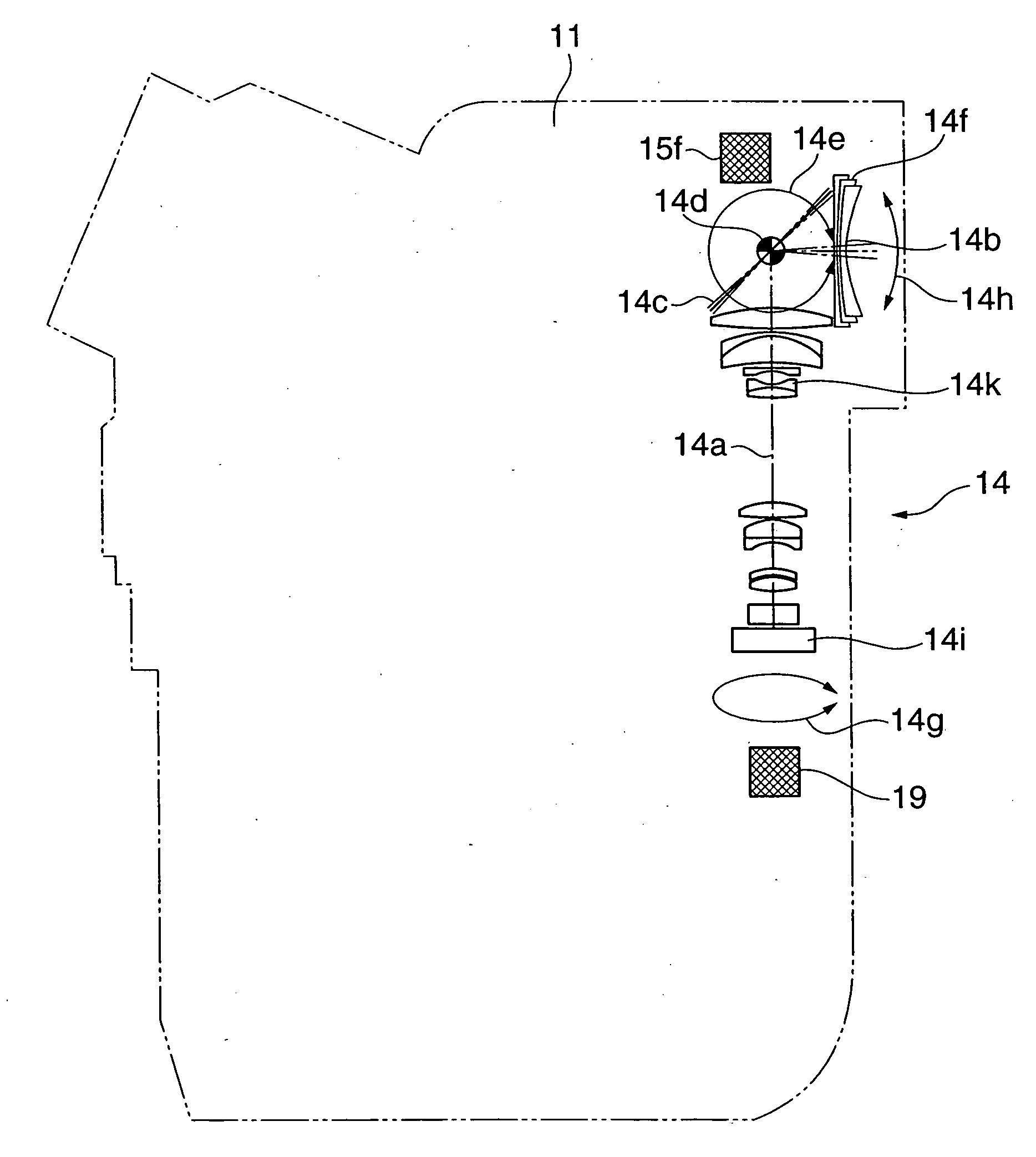
[0083]FIG. 1 is a schematic view showing the whole construction of a video camera as a photographing apparatus according to the present invention.

[0084] As shown in FIG. 1, a video camera body 11 is provided with a bending optical system 14 accommodated therein. In the video camera body 11, a main optical axis 14a of the bending optical system 14 extends in a vertical direction (along an axis approximately orthogonal to the horizontal plane on which the video camera is placed), bends (i.e. the direction of the main optical axis changes) at a mirror (reflection surface) 14c, and further extends from the mirror 14c toward an object. An angle formed by the main optical axis 14a and an object optical axis 14b (a part of the main optical axis 14a closer to the object with respect to the mirror 14c) changes according to the rotational position of the mirror 14c. When the mirror 14c is in its initial position, the angle formed by the two optical axes is 90 degrees. Object light having ente...

second embodiment

[0189] Next, a description will be given of the present invention.

[0190] The second embodiment is distinguished from the first embodiment described above only in the constructions of a tilting drive linkage and a panning drive linkage employed therein.

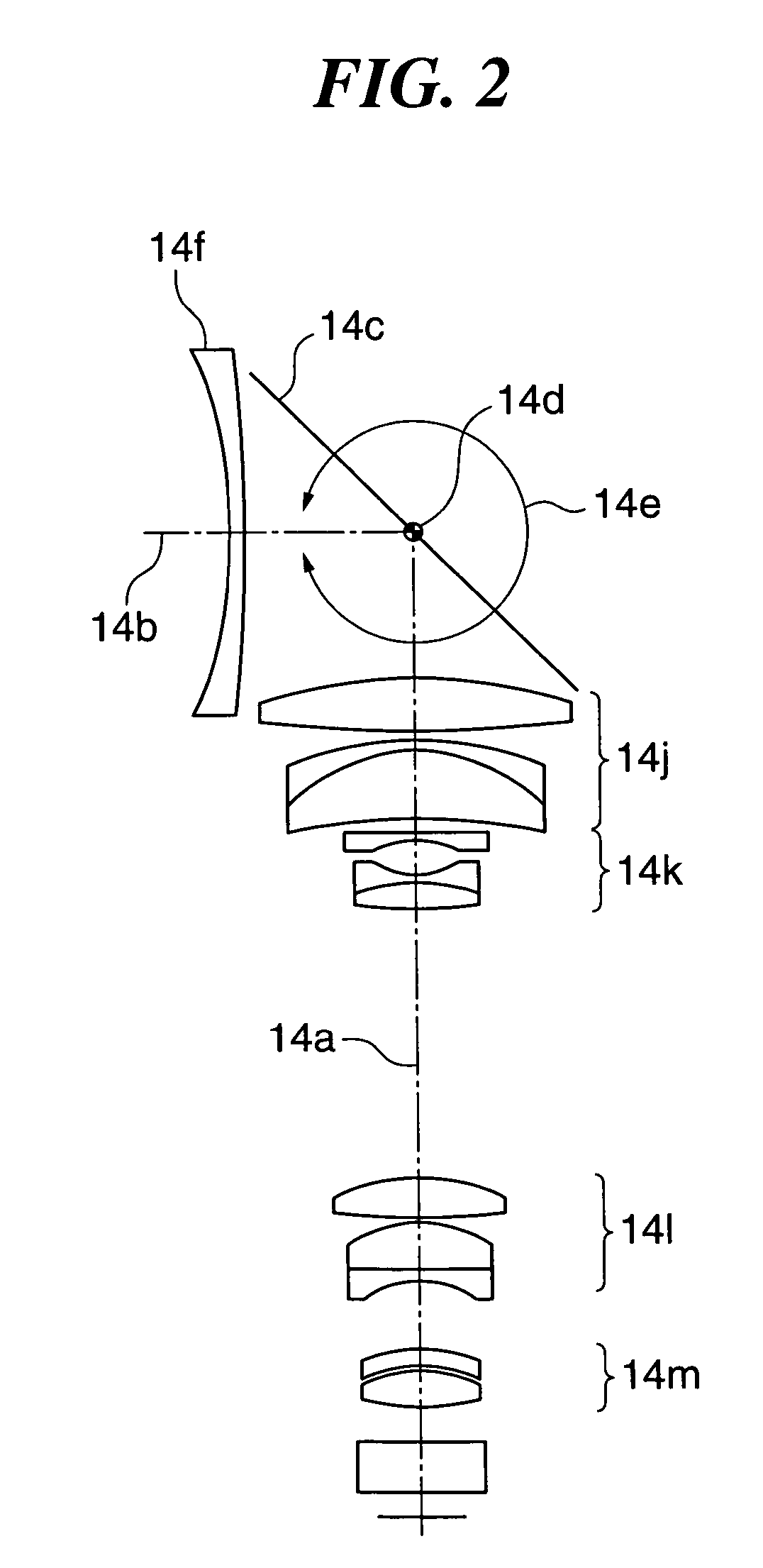
[0191]FIGS. 16A and 16B are views showing the tilting drive linkage of a photographing apparatus according to the second embodiment. The tilting drive linkage is a mechanism that drives the mirror 14c and the front lens 14f in unison. FIG. 16A is a side view of the tilting drive linkage as viewed from the bending optical system shown in FIG. 2, and FIG. 16B is a top plan view of the tilting drive linkage.

[0192] In FIGS. 16A and 16B, the front lens support frame 15a holding the front lens 14f is supported by the shaft 14d such that the front lens support frame 15a can rotate about the shaft 14d in the directions indicated by the double-headed arrow 14e along with the front lens 14f.

[0193] A front lens support frame pulley 15g is fixe...

third embodiment

[0204] Next, a description will be given of the present invention.

[0205] The third embodiment is distinguished from the above described first embodiment only in the construction of a tilting drive linkage and an electrical system configuration employed therein.

[0206]FIGS. 18A to 18C are views showing the tilting drive linkage of a photographing apparatus according to the third embodiment. The tilting drive linkage is a mechanism that drives the mirror 14c and the front lens 14f in unison. FIG. 18A is a side view, partly in section, of the tilting drive linkage as viewed from the bending optical system shown in FIG. 2, FIG. 18B a top plan view of the tilting drive linkage, and FIG. 18C a fragmentary view showing in detail a part of the tilting drive linkage.

[0207] In FIGS. 18A and 18B, the tilting drive linkage is different from the tilting drive linkage in FIGS. 5A and 5B in that the transmission lever 17a as a device for operating the front lens support frame 15a and the mirror s...


PUM


Abstract

A photographing apparatus which realizes a taking lens barrel whose shape is not largely changed during panning or tilting shot, thereby being compact in size and easy to handle. In the photographing apparatus, an image pickup device (14i) outputs an electric signal from object light. A bending optical system (14) has a front lens (14f) and lens groups (14j, 14k, 14l, and 14m) and a mirror (14c) disposed between the front lens and the laminated lens 14j, to guide the object light to the image pickup device. A panning actuator (19) and a tilt actuator (15f) cause the mirror and the front lens or the lens groups to be pivotally moved in unison about respective different axes to thereby change a shooting direction.

Description

BACKGROUND OF THE INVENTION [0001] 1. Field of the Invention [0002] The present invention relates to a photographing apparatus, such as a video camera, and a control method therefor. [0003] 2. Description of the Related Art [0004] Recently, in a video camera, operations, such as exposure determination, focusing, and shake correction, which are important for photographing, have been all automated, and hence even a photographer inexperienced in operating a camera seldom fails in photographing. [0005] There has also been proposed a video camera designed such that natural images can be obtained even when photographing is carried out while moving the camera intentionally during photographing, for example, performing a panning operation (an operation of horizontally moving the shooting direction of the camera) and / or a tilting operation (an operation of vertically moving the shooting direction of the camera) (see e.g. Japanese Laid-Open Patent Publication (Kokai) No. H11-275431). [0006] H...

Claims


Application Information

Patent Timeline
IPC IPC(8): G03B15/00
CPCG02B5/08G02B7/1805G02B7/1822G02B15/177H04N5/232G02B27/646G03B17/17H04N5/2259G02B26/0816G02B15/145H04N23/58H04N23/55H04N23/695
Inventor WASHISU, KOICHISUDA, YASUOTSUBOI, TAKAYUKI
Owner CANON KK
Why Eureka
Try Eureka