
Equalizer having tunable optical and electronic dispersion compensation

a technology of optical and electronic dispersion compensation and equalizer, which is applied in the direction of distortion/dispersion elimination, electromagnetic repeaters, fibre transmission, etc., can solve the problems of electronic dispersion compensation, edc, and fundamentally limited dispersion compensation they can provide, so as to reduce the overall distortion of the received optical signal

Inactive Publication Date: 2006-03-30
LUCENT TECH INC
View PDF19 Cites 45 Cited by
  • Summary
  • Abstract
  • Description
  • Claims
  • Application Information

AI Technical Summary

Benefits of technology

[0012] a controller responsive to the quality signal for generating the first control signal for controlling first-order dispersion compensation in the ODC and for generating the one or more control signals for controlling higher-order dispersion compensation and / or transmissivity ripple in the EDC so as to reduce overall dispersion in the received optical signal.
[0018] in response to the quality signal, controlling first-order dispersion compensation in the ODC and controlling higher-order dispersion compensation and / or transmissivity ripple in the EDC so as to reduce overall dispersion in the received optical signal.
[0024] a controller responsive to the quality signal for generating the first control signal for controlling first-order distortion compensation in the OEQ and for generating the second control signal for controlling higher-order distortion compensation in the EEQ so as to reduce overall distortion in the received optical signal.

Problems solved by technology

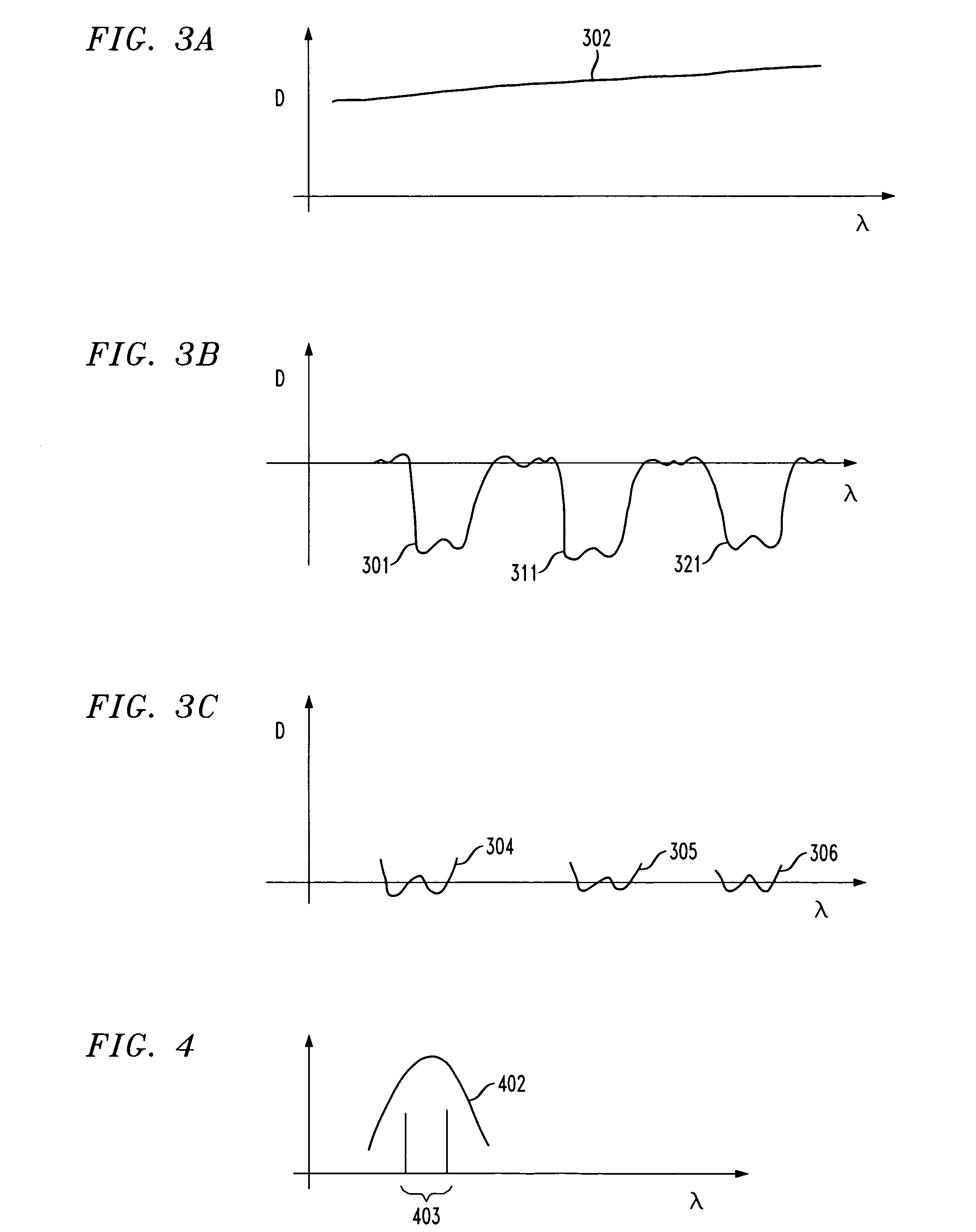
As a result, while these ODCs provide significant first-order dispersion compensation, they leave significant high-order dispersion and transmissivity ripple effects.
It is known that electronic dispersion compensation, EDC, is fundamentally limited in the amount of dispersion compensation they can provide, because of the loss of phase information in the photodetector (A. J. Weiss, et al, IEEE Photon. Technol. Lett., 15 (2003), p.

Method used


Image

  • Equalizer having tunable optical and electronic dispersion compensation
  • Equalizer having tunable optical and electronic dispersion compensation
  • Equalizer having tunable optical and electronic dispersion compensation

Examples


Embodiment Construction

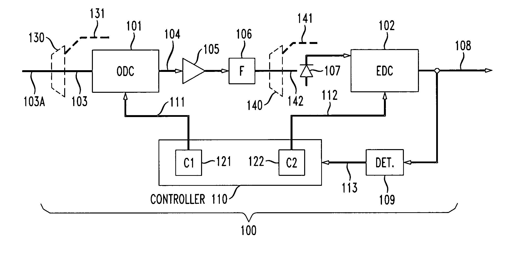
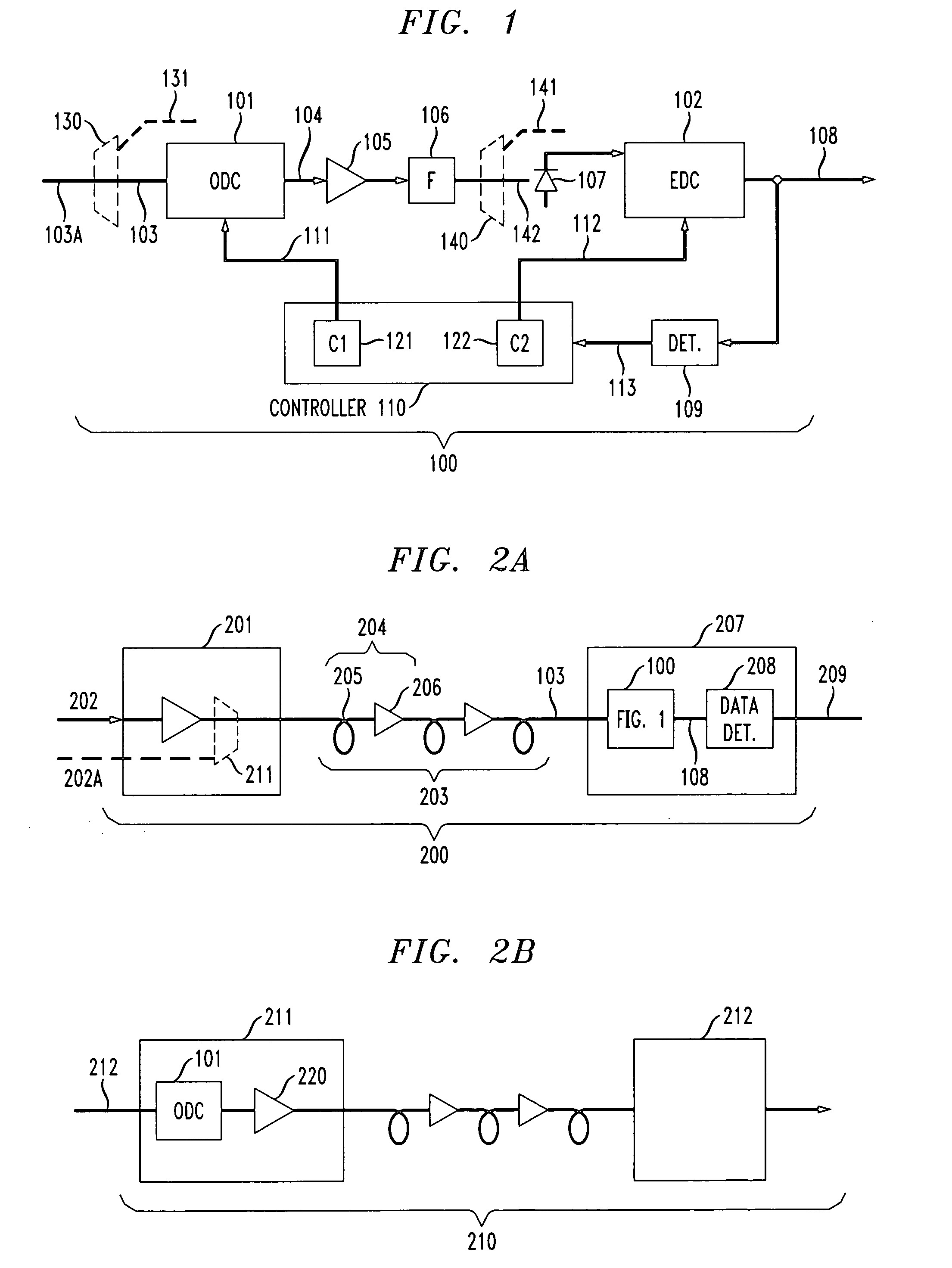
[0035] Shown in FIG. 1 is an illustrative block diagram of our dispersion compensator 100 including adjustable (or tunable) Optical Dispersion Compensator (ODC) 101 and adjustable Electrical Dispersion Compensator (EDC) 102 for providing dispersion equalization of a received optical signal 103. With reference to FIG. 2A, our dispersion compensator 100 may be illustratively part of a receiver unit 207 of an optical communication system 200. In such a system, a data modulated optical signal 202 is amplified and transmitted by optical transmitter 201 over an optical facility 203 to a receiver unit 207. The optical facility 203 is typically an optical fiber that may or may not include a segment of dispersion compensating fiber (DCF). The optical facility 203 may include one or more optical links 204 including an optical repeater 206 and optical fiber 205. As a result of transmission over optical facility 203, the modulated optical signal experiences optical dispersion, transmission ripp...


PUM


Abstract

A method of and apparatus for optical signal dispersion compensation uses tunable optical (ODC) and electronic (EDC) dispersion compensation. The ODC provides significant first-order dispersion compensation, but leaves significant high-order dispersion and transmissivity ripple effects. The EDC is used to provide compensation for the high-order dispersion and transmissivity ripple from the ODC.

Description

TECHNICAL FIELD OF THE INVENTION [0001] This invention relates generally to optical and electrical equalization arrangements and, more particularly, to a method and apparatus for implementing an equalizer having tunable optical and electronic chromatic dispersion compensation. BACKGROUND OF THE INVENTION [0002] Currently, to transmit over more than 80 km of standard single-mode fiber (SSMF) at 10 Gb / s requires chromatic dispersion compensating fiber (DCF). DCF is expensive, large, lossy, nonlinear, and fixed. The fixed nature is especially problematic for mesh networks in which transmission path-length may vary. [0003] Also, there is a new type of 10-Gb / s optical transceiver that promises to have extremely low cost—the 10-Gb / s pluggable transceiver (XFP). This is a small module (9 mm×18 mm×62 mm) that can be plugged into a cage on the faceplate of a circuit pack. It contains a low-cost electroabsorption modulated laser (EML), a receiver, and clock and data recovery chips. EMLs canno...

Claims


Application Information

Patent Timeline
Patent Type & Authority Applications(United States)
IPC IPC(8): H04B10/12H04B10/29
CPCH04B10/2513
Inventor CHANDRASEKHAR, SETHUMADHAVANDOERR, CHRITOPHER RICHARD
Owner LUCENT TECH INC
Learn More