Honeycomb structure

a technology of honeycomb and structure, applied in the field of honeycomb structural body, can solve the problems of high gas flow amount, high amount of particulate caught, and easy violent combustion

Active Publication Date: 2006-03-30
IBIDEN CO LTD
View PDF18 Cites 83 Cited by
  • Summary
  • Abstract
  • Description
  • Claims
  • Application Information

AI Technical Summary

Benefits of technology

[0034] Further, in the honeycomb structural body, the porous ceramic member is desirable that a half-width value of a peak of silicon (Si) (2θ=about 28°) in an X-ray diffraction is not more than 0.6°.
[0035] In the honeycomb structural body of the invention, it is desirable that as the through-hole are used two kinds of through-holes constituting a group of large volume through-holes plugged at one end portions with a plugging material and a group of small volume through-holes plugged at the other end portions with a plugg

Problems solved by technology

In addition, the amount of particulates caught is relatively equal or higher in the direct inflow partition, and hence violent combustion is liable to cause at the direct inflow partition.
Therefore, the most violent combustion occurs at such a place that the flow amount of the gas is high and the amount of particulate caught is high.
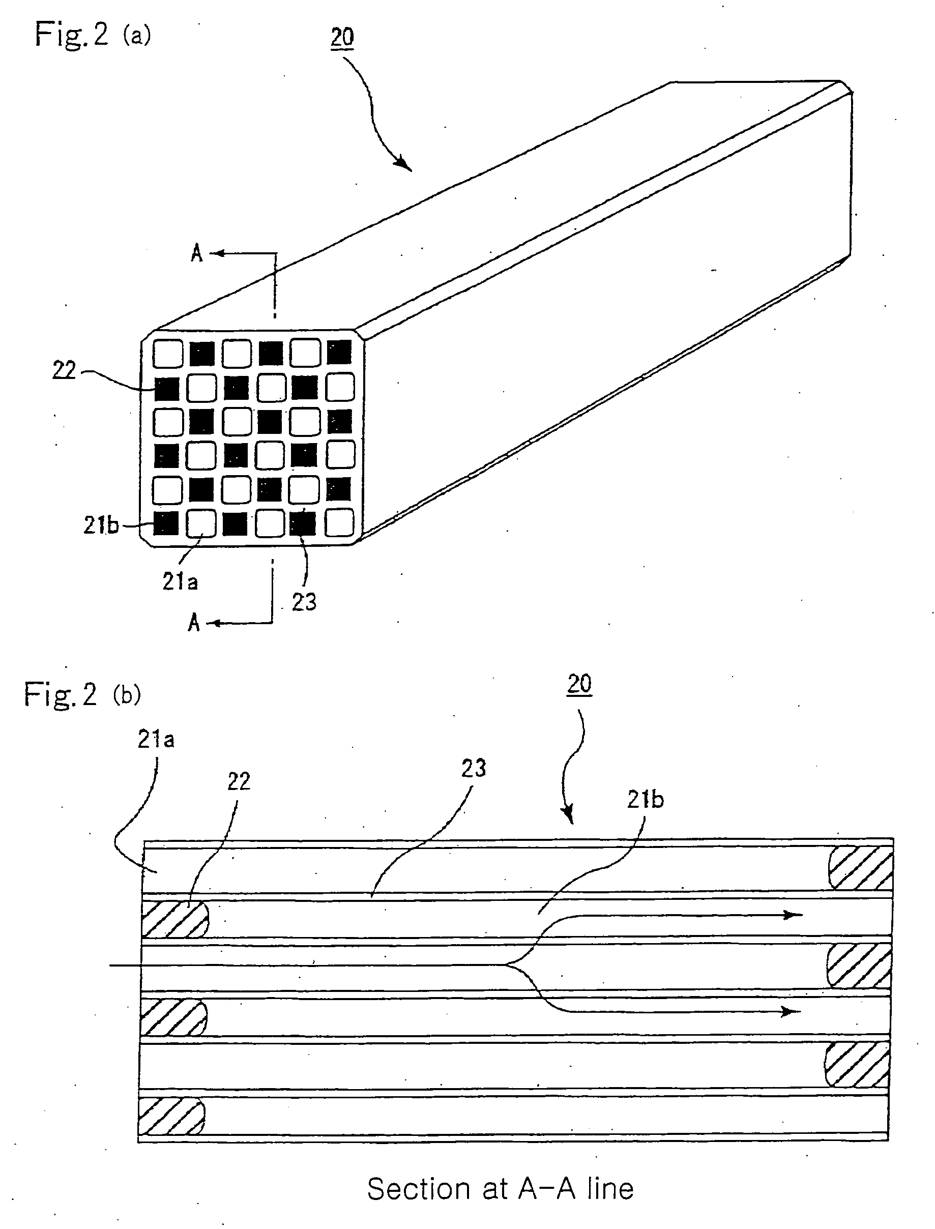
That is, it is considered that violent combustion easily occurs in the vicinity of a place contacting the direct inflow partition with the indirect inflow partition.
Therefore, when such a honeycomb structural body is used as a filter and regeneration treatment of such a filter is conducted, an uneven temperature distribution is caused by the combustion of particulates to locally apply a large thermal stress, so that a vital defect such as crack or the like occurs in the exhaust gas filter, and as a result, there

Method used


Image

  • Honeycomb structure
  • Honeycomb structure
  • Honeycomb structure

Examples


example 1

[0211] Example 1 prepares three kinds of ceramic porous bodies having different sectional shapes of through-holes (B1-B3) shown in FIGS. 4(a)-(c) by the following method (B) using a raw material paste A1 prepared by the following method (A) and consisting essentially of silicon carbide powder and monocrystal silicon powder, and prepares three kinds of assembly type honeycomb structures bundling a plurality of these ceramic porous bodies through sealing material layers as Examples 1.1-1.3.

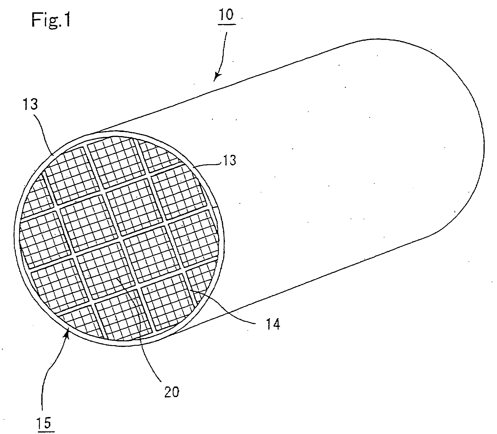
[0212] Also, there are prepared three kinds of ceramic blocks having different sectional shapes of through-holes (B4-B-6) as shown in FIGS. 13, 14 and 15 using the raw material paste A1, and prepared three kinds of integral type honeycomb structures from these ceramic blocks as Examples 1.4-1.6. A concrete explanation is made below.

(A) Preparation of Raw Material Paste A1

[0213] A raw material paste is prepared by mixing 80 wt % of α-type silicon carbide powder having a mean particle size of 30 μm...

example 2

[0252] On the assumption that the porous ceramic member is composed of silicon-silicon carbide composite by bonding silicon carbides with silicon in the same manner as in Examples 1.1-1.6, Example 2 prepares ceramic members having changes porosities as Examples 2.1-2.5.

[0253] Moreover, the shapes of the porous ceramic members in Examples 2.1-2.5 are fixed to the same shape as in the through-hole sectional shape B1 (FIG. 4(a)), and the material forming the member (raw material paste) is adjusted to prepare five kinds of different honeycomb structural bodies.

[0254] (1) At first, a raw material paste is prepared by mixing 80 wt % of α-type silicon carbide powder having a mean particle size of 20 m as a raw material powder having a relatively large mean particle size (called as “powder A”) and 20 wt % of monocrystal silicon powder having a mean particle size of 6 μm as a raw material powder having a relatively small mean particle size (called as “powder B”) and adding and kneading wit...

example 3

[0263] Example 3 prepares porous ceramic members by changing a surface roughness (Ra) of a partition on the assumption that the porous ceramic member is made of silicon-silicon carbide composite body formed by bonding silicon carbides with silicon likewise Example 2, and prepares an assembly type ceramic structural body made by bundling a plurality of these members as Examples 3.1-3.7.

[0264] Moreover, 7 kinds of different honeycomb structural bodies are prepared by fixing through-hole sectional shapes of the porous ceramic members in Examples 3.1-3.7 to the same shapes as B1 (FIG. 4(a)) likewise Example 2, and adjusting the aspect ratio of the material forming the member (raw material paste), particularly acrylic resin particles and / or the surface roughness of the die.

[0265] (1) At first, a raw material paste is prepared by mixing 5 vol % of acrylic resin particles (density: 1.1 g / cm3) as a pore forming material having a mean particle size of 11 μm and an aspect ratio of 1 with 80...


PUM

PropertyMeasurementUnit
Thicknessaaaaaaaaaa
Angleaaaaaaaaaa
Angleaaaaaaaaaa

Abstract

It is to provide a honeycomb structural body having an excellent durability, which is large in the catching amount of particulates per unit volume and does not cause uneven accumulation of ash and occurrence of cracks or the like even in use for a long period of time, and there is proposed a honeycomb structural body obtained by assembling one or plural porous ceramic members in which two kinds of through-holes consisting of a group of large volume through-holes and a group of small volume through-holes are arranged side by side in the longitudinal direction through partitions and either one ends of these through-holes are plugged, wherein the ceramic member is made of silicon-ceramic composite material consisting of ceramic and silicon.

Description

INDICATION OF THE RELATED APPLICATION [0001] The present application is an application claiming priority of JP 2003-178797 filed on Jun. 23, 2003. TECHNICAL FIELD [0002] This invention relates to a honeycomb structural body used as a filter for removing particulates and the like in an exhaust gas of a vehicle discharged from internal combustion engines such as diesel engine and the like, or a catalyst carrier or the like. BACKGROUND ART [0003] It has been known that an exhaust gas discharged from an internal combustion engine of a vehicle such as buses, trucks or the like or a construction vehicle contains particulates having a harmful effect on environment and the human body, and techniques for removing the particulates are required. As one of such techniques, there is, for example, a honeycomb structural body (filter) for the exhaust gas purification in which the exhaust gas is passed through a porous ceramic member to catch and remove the particulates. [0004] As a concrete embodi...

Claims


Application Information

Patent Timeline
IPC IPC(8): B32B3/12B01J35/04C04B35/565C04B35/636C04B35/64C04B35/80C04B38/00F01N3/022F01N3/28
CPCB01J35/04Y10T428/24149C04B35/6263C04B35/63C04B35/632C04B35/6365C04B35/64C04B35/806C04B38/0006C04B2111/00793C04B2111/0081C04B2235/3418C04B2235/3826C04B2235/383C04B2235/3834C04B2235/428C04B2235/449C04B2235/5224C04B2235/5228C04B2235/5436C04B2235/5445C04B2235/661C04B2235/767C04B2235/77C04B2235/80C04B2235/9607F01N3/0222F01N3/2828F01N2330/06F01N2330/34F01N2330/48F01N2450/28C04B35/565Y10T428/24174Y10T428/24157Y10T428/24744Y02T10/20C04B38/0074C04B38/0051Y02T10/12C04B35/80B01D53/84F01N3/28
Inventor KOMORI, TERUOOHNO, KAZUSHIGEHONG, SUNGTAESATO, HIROKI
Owner IBIDEN CO LTD
Why Eureka
Try Eureka