Polymeric piezoresistive sensors

a piezoresistance sensor and polymer technology, applied in the field of piezoresitive sensors, can solve the problems of small piezoresistance coefficients in gold compared to those of silicon, reduced sensitivity, and very stiff silicon

Inactive Publication Date: 2006-04-06
CALIFORNIA INST OF TECH
View PDF12 Cites 53 Cited by
  • Summary
  • Abstract
  • Description
  • Claims
  • Application Information

AI Technical Summary

Problems solved by technology

However, silicon is very stiff, with a Young's modulus of 1011 Pa which reduces sensitivity.
However, the piezoresistance coefficients in gold are small compared to those of silicon.
However, the system requires unobstructed optical access to the membrane which prevents integration of force actuators and microfluidics.

Method used


Image

  • Polymeric piezoresistive sensors
  • Polymeric piezoresistive sensors
  • Polymeric piezoresistive sensors

Examples


first embodiment

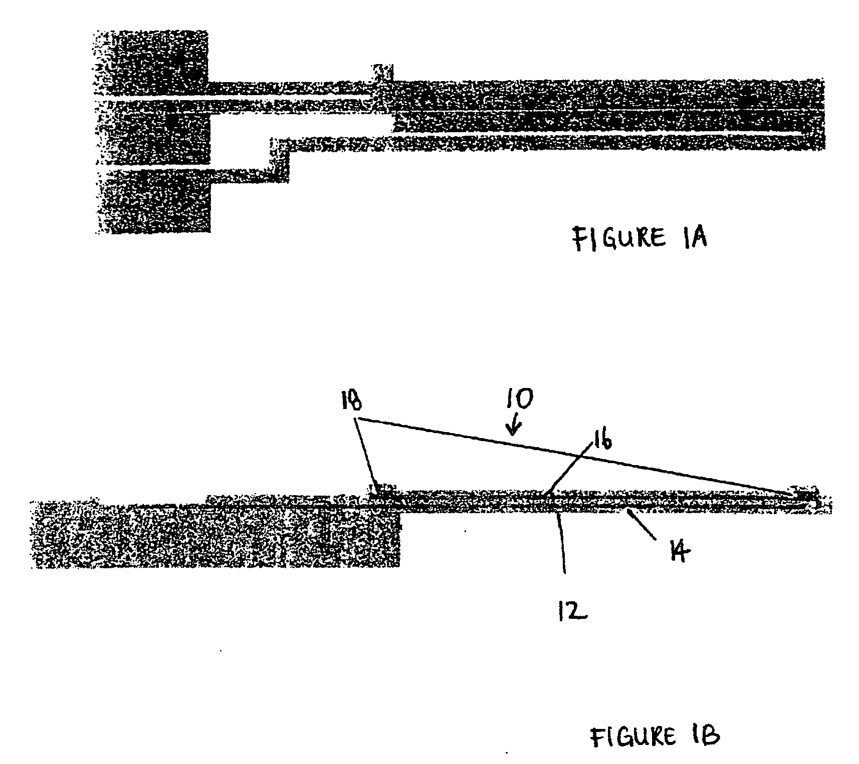
[0018] In a first embodiment, a sensor comprising a thin film transistor sensing element 10 and a resonator 12 is described. However, it should be noted that a scanning probe microscope (SPM) tip, such as atomic force microscopes (AFM) tip may also have a similar configuration. The micromechanical resonator 12 is in the form of a simple force sensing cantilever (i.e., a microcantilever having a thickness of 10 microns or less). The cantilever 12 preferably comprises a polymer cantilever, such as a parylene cantilever. Other organic polymer materials such as Su8 may also be used. Inorganic materials such as semiconductors (e.g. silicon (Si) and gallium arsenide (GaAs)) and insulators (e.g. silicon dioxide (SiO2) and silicon nitride (Si3N4)) may also be used as cantilever materials.

[0019] The thin film transistor10 preferably comprises an all organic thin film transistor which is located on a cantilever 12. The transistor 10 functions as the piezoresistive sensing element for the can...


PUM


Abstract

A MEMS system, such as a biosensor, includes a micromechanical resonator and a piezoresistive sensing element which includes an organic semiconductor, such as an organic thin film transistor.

Description

CROSS-REFERENCE TO RELATED PATENT APPLICATIONS [0001] This application claims benefit of priority of U.S. Provisional Application Ser. No. 60 / 602,113, filed on Aug. 17, 2004, and U.S. Provisional Application Ser. No. 60 / 602,099, filed on Aug. 17, 2004. All of the above mentioned applications are incorporated herein by reference in their entirety.BACKGROUND OF THE INVENTION [0002] This invention is related specifically to piezoresitive sensors for microelectromechanical systems (MEMS), and specifically to organic semiconductor piezoresistive sensors. [0003] Microelectromechanical systems (MEMS) include devices with features having a size less than 100 microns in at least one dimension, and preferably in two or three dimensions. Preferably, these features comprise movable features or elements, such as cantilevers, diaphragms, clamped beams, wires, etc. Microelectromechanical systems include, but are not limited to, scanning probe microscopes (SPM), such as atomic force microscopes (AF...

Claims


Application Information

Patent Timeline
Patent Type & Authority Applications(United States)
IPC IPC(8): H01L29/82
CPCG01N27/414G01N29/036G01N2291/0257
Inventor AXELROD, BLAKE W.ROUKES, MICHAEL L.
Owner CALIFORNIA INST OF TECH
Why Eureka
Try Eureka