Color image pickup device and color light-receiving device

a pickup device and color technology, applied in the field of color image pickup devices and light-receiving devices, can solve the problems of false color production, loss of light, and light amount decrease, and achieve the effect of high color separation capability and high sensitivity

Inactive Publication Date: 2006-10-31
CANON KK
View PDF9 Cites 104 Cited by
  • Summary
  • Abstract
  • Description
  • Claims
  • Application Information

AI Technical Summary

Benefits of technology

[0014]In view of the above-described situation, the present invention provides an image pickup device having a high sensitivity, having a high level of color separation capability and being free of color false.

Problems solved by technology

However, the color filter system has the following problems: (1) the light amount decreases because a part of light is absorbed by the color filter; and (2) a false color is produced because color separation is done by detecting different colors at different locations.
Also, an optical lowpass filter is required for preventing the problem of false color, and a loss of light occurs also in this case.
In the multiple plate system, on the other hand, a high accuracy prism or color separating film (dichroic mirror) is required, and a high level of registration technique is required, thus raising problems such that the cost is increased, the equipment is scaled up and a loss of light occurs in an optical device such as a prism.
This image pickup device is effective for the false color, but has a disadvantage that as far as using light penetration depth dependence on the wavelength in Si, the spectrum range detected in each stacked light-receiving part is broad, and thus color separation is inadequately performed.
This raises a problem such that the amount of light substantially converted into a signal decreases to reduce the sensitivity.
Also, color separation can be controlled to some extent by designing the depth of the P-N junction of each light receiving part, but there is a tradeoff relationship between the sensitivity and the color separation, and the design is severely limited, for example the improvement in color separation results in a reduction in sensitivity.
It is especially difficult to achieve compatibility between the sensitivity and the color separation for green of high visual sensitivity.
For example, in an ordinary visible color image sensor, red, green and blue have peak sensitivities at about 450 nm, about 550 nm and about 650 to 700 nm, respectively, but this device is poor in color purity because the sensitivity peak of green is at 500 nm, which is slightly shifted toward the short wavelength region, and the sensitivity of red is shifted toward the long wavelength region.
In addition, due to the three-layer stacked structure, structures such as a wiring are complicated, fabrication work becomes difficult, and thus the cost is increased.

Method used


Image

  • Color image pickup device and color light-receiving device
  • Color image pickup device and color light-receiving device
  • Color image pickup device and color light-receiving device

Examples


example 1

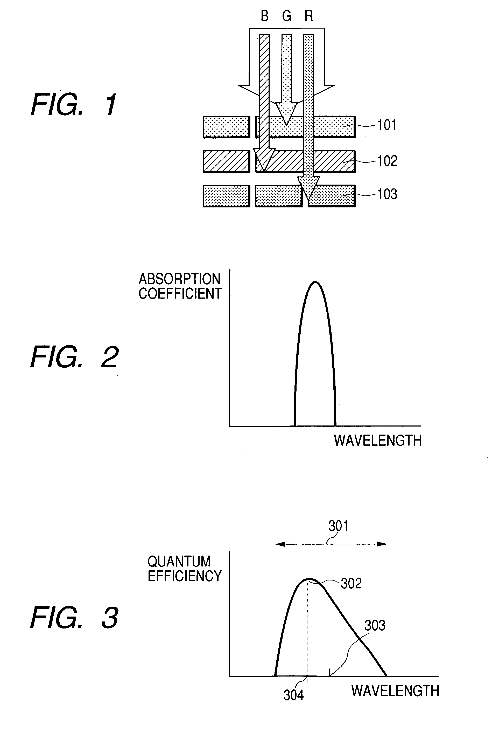
[0138]In this Example, the superiority of the image pickup device having a configuration shown in FIG. 1 was demonstrated by numerical estimation.

[0139]As shown in FIG. 1, the image pickup device is a stacked type image pickup device in which a light-receiving part 101 for detecting green light, a light-receiving part 102 for detecting blue light, and a light-receiving part 103 for detecting red light are stacked in this order. The light-receiving part constituted by an organic semiconductor having a peak of an absorption spectrum for green light is used, and light-receiving parts made of silicon for blue light and red light are used, as a model case. Blue light and red light are separated using a difference in absorption length in silicon.

[0140]In the configuration used here, the first light-receiving part corresponds to the green light-receiving part, and the second light-receiving part corresponds to the blue light-receiving part and the third light-receiving port corresponds to ...

example 3

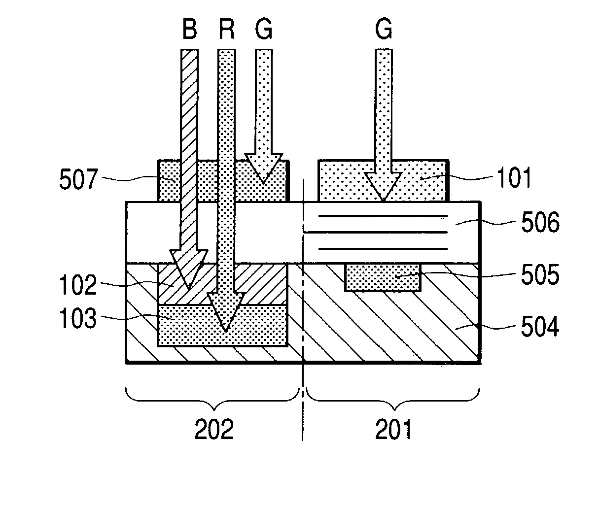
[0162]In this Example, an organic light-receiving part for green light was used for the uppermost layer, an organic light-receiving part for blue light was used for the middle layer, and a light-receiving part made of silicon was used for the lowermost layer. The structure is shown in FIG. 15. For reading the signal, a CCD 1205 in a silicon substrate 1204 is used for blue and green as well as red. The CCD was an interline-type CCD.

[0163]First, based on the usual method of fabricating a CCD, a red light-receiving part 1203 and a charge transfer part were fabricated in the silicon substrate, and organic light-receiving devices for blue and green were stacked thereon in this order in the same manner as Example 2 to fabricate the CCD. DCM 1 was used for the light-receiving layer of blue light-receiving part 1202, and eosine Y was used for the green light-receiving layer 1201.

[0164]In the light-receiving part, a zinc oxide film with the thickness of 100 nm was formed by the spattering me...

example 4

[0167]This Example shows an example of a color line sensor, as shown in the outlined sectional view of the pixel area in FIG. 16, in which an organic light-receiving device 1101 for green light was placed as the uppermost layer, and a light-receiving part 1102 made of a-Si capable of performing color separation for blue and red by the absorption length, and further a TFT, capacitor or the like 1104 made of a-Si were placed as the lower layer on a glass substrate 1103.

[0168]First, a glass substrate having a TFT transistor made of amorphous Si (a-Si) was prepared. Subsequently, a p-i-n-i-p-type tandem a-Si light-receiving part was prepared. The thicknesses of their type layers were 80 nm, 700 nm, 180 nm, 90 nm and 10 nm in the order from the bottom layer. This a-Si light-receiving part is capable of making the switch between the reception of light in an upper pin part and the reception of light in a lower pin part by switching the voltage between +2.5 V and −2.5 V. The a-Si was formed...


PUM


Abstract

A light-receiving device comprises, on a substrate, a first light-receiving part for detecting light of a first wavelength range, and a second light-receiving part for detecting light of a second wavelength range. At least a part of incident light is transmitted through the first light-receiving part and then received by the second light-receiving part. The central wavelength of the first wavelength range is longer than the central wavelength of the second wavelength range, and the first light-receiving part is composed of an organic semiconductor having an absorption spectral maximum in the first wavelength range.

Description

BACKGROUND OF THE INVENTION[0001]1. Field of the Invention[0002]The present invention relates to a color image pickup device and a light-receiving device.[0003]2. Related Background Art[0004]Conventionally, as light-receiving devices, devices using p-n junctions or p-i-n junctions of compound semiconductors such as crystalline silicon, amorphous silicon and GaAs have been generally used. These light-receiving devices are two-dimensionally arranged to form a plane-type image pickup device, or one-dimensionally arranged to form a line sensor.[0005]In the color image pickup device and line sensor, a color filter system in which color filters each allowing light of a specific wavelength range to pass through are placed is generally used for color separation. That is, in the color image pickup device, color filters 701 are placed on the top of CCD or CMOS sensors 702 as shown in FIGS. 22A and 22B. Examples of color filter systems include a color filter system in which color filters of th...

Claims


Application Information

Patent Timeline
Patent Type & Authority Patents(United States)
IPC IPC(8): H01L31/00
CPCH01L27/302H01L27/307H01L31/101H01L51/4233H01L51/4246H01L27/14621H01L27/14647H01L51/0054H01L51/0064H01L51/0081H01L51/428H01L2251/308Y02E10/549H10K30/57H10K39/32H10K85/652H10K85/622H10K85/324H10K30/152H10K30/211H10K30/65H10K2102/103
Inventor IWASAKI, TATSUYA
Owner CANON KK
Why Eureka
Try Eureka