

Permanent magnet type electric rotating machine and wind turbine electric power generation system
a permanent magnet type, electric power generation system technology, applied in the direction of magnetic circuit rotating parts, electric generator control, magnetic circuit shape/form/construction, etc., can solve the problems of increasing the building cost of the wind turbine power generation system, increasing the running cost of the rotating machine, etc., to increase the cooling efficiency of the permanent magnet type
- Summary
- Abstract
- Description
- Claims
- Application Information
AI Technical Summary
Benefits of technology
Problems solved by technology
Method used
Image

Examples
embodiment 1
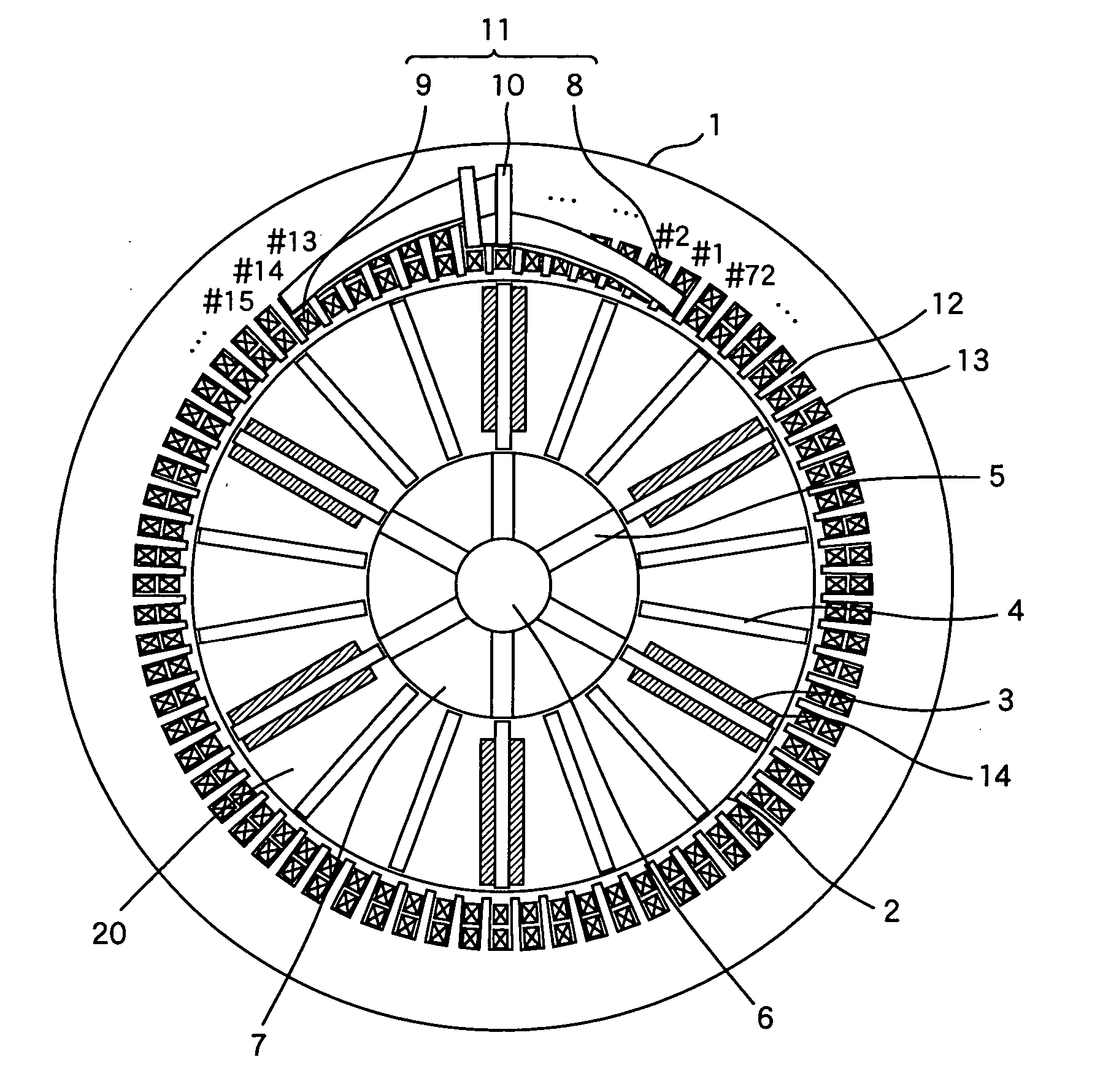
[0035]FIG. 1 is a cross sectional view of a generator of 6-pole and 72 slots permanent magnet type according to the present invention. This electric rotating machine is suitable for a wind turbine electric power generator of a several MW class. The generator allows a rotation speed of 1000 to 2000 rpm.
[0036] The stator 1 has a distributed winding coil wound around stator teeth 12. The coil 11 comprises three phase windings of UVW to constitute 6 poles by 72 slots. The coil 11 is constituted by upper coils 8 and lower coils 9 inserted into the slots 13 between the teeth 12 of the stator in addition to coil ends 10.
[0037] In the first embodiment, the coils 11 are wound in a manner called a full-pitch winding, whereby the coil 11 that comes out conveniently from #1 to # 72 in the anticlockwise direction goes into the upper coil 8 in the #13 slot, which is designated by adding 12 obtained by dividing the number of slots (72) with the number of poles (6) to the # 1 slot. This continues...
embodiment 2
[0050]FIG. 16 shows a cross sectional view of a second embodiment of a generator of a 6-poles and 72 slots permanent magnetic type electric rotating machine according to the present invention. The stator 1 is a distribution winding stator that has coils 11 wound distributedly on the stator teeth 12. The coils 11 have three phase windings for UVW to electrically constitute 6 poles in 72 slots. The coils 11 are constituted by the upper coil 8 and the lower coil 9 disposed in the stator slots 13 between the stator teeth 12 and coil ends 10.
[0051] In the second embodiment, the coils 11 are wound in a manner called a short-pitch winding. The coil that comes out from the lower coil 9 in the # 1 slot of the slots #1 to # 72, which are numbered conveniently in the anti-clockwise direction for the stator slots 13 enters into the upper coil 8 in # 11 slot, to which 10 that is less than 12 obtained by dividing the number 72 with the number of poles 6. This continues in the circumferential dir...
embodiment 3
[0052]FIG. 17 shows a wind turbine electric power generation system to which the present invention is applied. The electric rotating machines shown in the first embodiment and the second embodiment 111 are connected to a wind turbine 114 by means of a speed up gear 113. The electric rotating machine 111 is connected to the electric power transmission system 116 by means of an electric power converter 115 to conduct electric power generation operation. In this embodiment, the wind turbine system as a driving force may be substituted by other driving forces such as water turbines, engines, gas turbines. Among the applications, the electric rotating machine of the embodiments may be most effectively applied to the wind turbine power generation system. The wind turbine 114 may be directly connected to the electric rotating machine 111. The above described embodiments are particularly advantageous for large scale wind turbine power generation systems because cooling of the electric rotat...
PUM
 Abstract
Description
Claims
Application Information