Confocal reflectance microscope system with dual rotating wedge scanner assembly

a microscope system and wedge scanner technology, applied in the field ofconfocal microscopes, can solve the problems of reducing the lateral resolution of the array, difficult to use, and the optics in the beam scanning mechanism of these instruments are large and bulky, and achieve the effect of small size and low cos

Inactive Publication Date: 2006-04-06
NORTHEASTERN UNIV
View PDF17 Cites 37 Cited by
  • Summary
  • Abstract
  • Description
  • Claims
  • Application Information

AI Technical Summary

Benefits of technology

[0008] The present invention relates to a confocal reflectance microscope capable of producing images of tissue such as skin with a quality comparable to that of current commercial instruments, but with a smaller size and at lower cost. The device uses a scanner system in which the optical path is passed through two wedges, which are rotated about the beam axis at variable speeds, resulting in coverage over a circular area.

Problems solved by technology

However, these resolutions are not suitable for imaging skin.
However, the line scanner is only confocal in one dimension, thereby decreasing the lateral resolution of the direction of the array.
Thus, the optics in the beam scanning mechanisms of these instruments tend to be large and bulky and difficult to use.

Method used


Image

  • Confocal reflectance microscope system with dual rotating wedge scanner assembly
  • Confocal reflectance microscope system with dual rotating wedge scanner assembly
  • Confocal reflectance microscope system with dual rotating wedge scanner assembly

Examples


Embodiment Construction

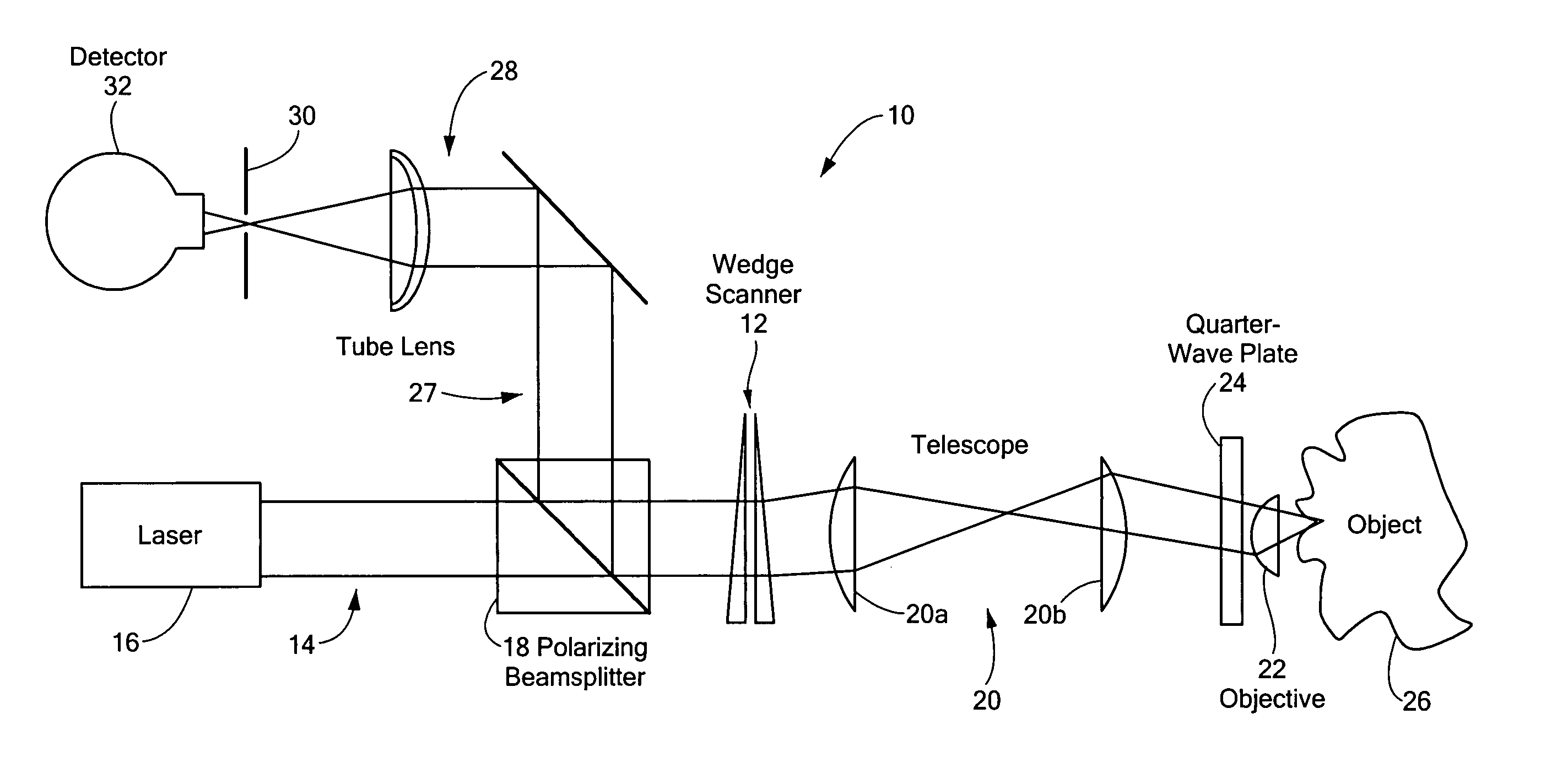
[0020] A confocal reflectance microscope system 10 with a dual-wedge scanner assembly 12 is illustrated in FIG. 1. An optical path 14 begins at a light source 16, such as a laser, which has a strong degree of polarization. The power of the laser can be controlled to permit varying the depth of imaging as known in the art. The beam on the optical path passes through a polarizing beam splitter 18, with P polarization, and then through the dual rotating wedge scanner assembly 12, described further below. Next, the beam passes through a telescope lens assembly 20 that properly aligns the beam with the pupil of an objective lens 22 or lens assembly of the microscope. En route to the objective, the path passes through a quarter-wave plate 24, having an axis oriented at 45° to the laser polarization, after which the objective focuses the beam onto the sample or object 26.

[0021] The light is either absorbed, scattered, or reflected at various locations within the sample. Some of the light ...


PUM


Abstract

A confocal reflectance microscope system incorporates a dual-wedge laser scanner assembly. The scanner assembly incorporates a pair of rotatably mounted prisms, each prism having an angle selected to deviate a light beam from a light source by a desired angle. Each prism is mounted for rotation at a desired speed of rotation and in a desired direction to scan the light beam over the target. An image is built up from successive reflected signals returned from the target.

Description

CROSS REFERENCE TO RELATED APPLICATIONS [0001] This application claims the benefit under 35 U.S.C. § 119(e) of U.S. Provisional Patent Application No. 60 / 616,483, filed on Oct. 6, 2004, the disclosure of which is incorporated by reference herein.STATEMENT REGARDING FEDERALLY SPONSORED RESEARCH OR DEVELOPMENT [0002] N / A BACKGROUND OF THE INVENTION [0003] A confocal microscope uses a point source of light, such as a focused laser beam, to illuminate a point within the sample. Scattered light from the focused spot is then imaged onto a detector through a point aperture such as a pinhole. The light source, illuminated spot and detector aperture lie in optically conjugate focal planes. The size of the detector aperture is matched to the size of the illuminated spot, thereby blocking any light that is not contributed from the back-scatter of the focused spot. By scanning the focused spot over the sample, the detector only receives light from the thin plane at the focus. Light from out-of-...

Claims


Application Information

Patent Timeline
Patent Type & Authority Applications(United States)
IPC IPC(8): G02B21/00
CPCG02B21/0032G02B21/0036G02B21/0052
Inventor DIMARZIO, CHARLES A.WARGER, WILLIAM C. II
Owner NORTHEASTERN UNIV
Why Eureka
Try Eureka