
Method for making a lens and an apparatus for precise pressing both sides of the lens

a technology of lens and pressing device, which is applied in the field of making lenses, can solve the problems of not being suitable for mass production with high productivity, and achieve the effect of constant installation dimensions

Active Publication Date: 2006-04-06
DOCTER OPTICS SE
View PDF16 Cites 10 Cited by
  • Summary
  • Abstract
  • Description
  • Claims
  • Application Information

AI Technical Summary

Benefits of technology

[0021] It is an object of the present invention to provide a method for manufacturing a lens for a motor vehicle headlight, which has a first convex lens surface and a second lens surface on opposite sides of the lens, is economical and guarantees constant installation dimensions.
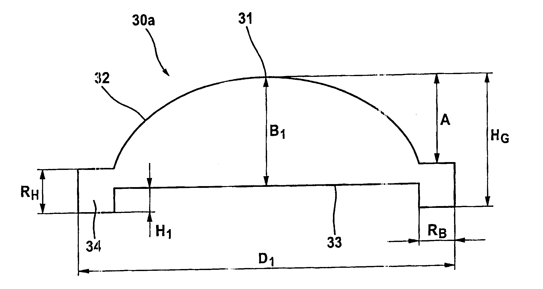
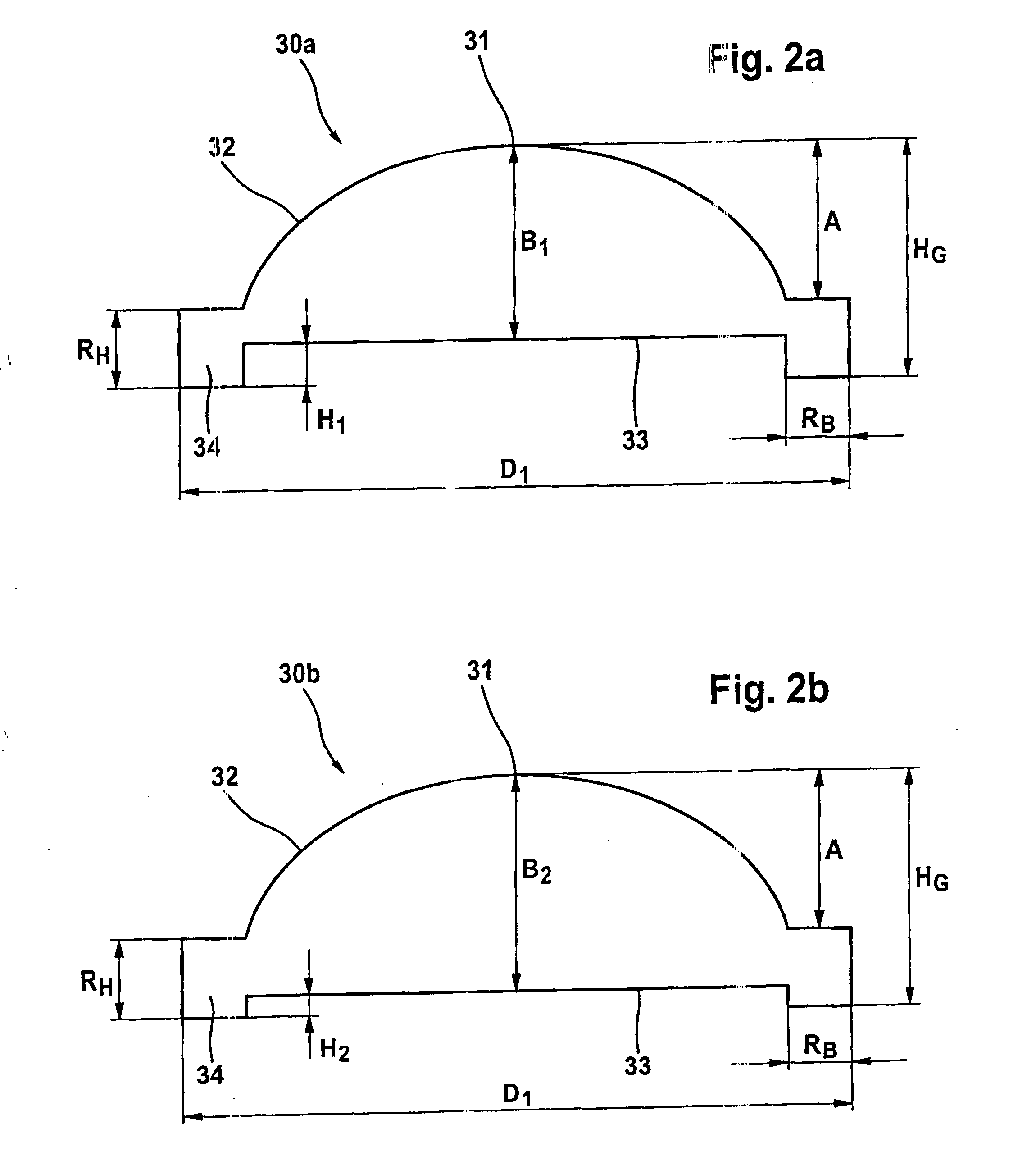
[0030] The supporting rim shown protrudes at least about H>0.2 mm from the highest point of the second lens surface. This feature is required so that the lens, which is precise pressed on both sides from the melt, subsequently can be deposited on a cooling conveyor, without damaging the second lens surface during the tempered cooling occurring on the cooling conveyor.
[0039] The precise pressing both sides of the lens previously seen as expensive is changed to a rapid and economical method for mass-producing the lenses when the precise pressing occurs directly from the melt. Moreover a supporting rim and a cooling process are of course required. This is not disadvantageous since this supporting rim can be used to establish the installation dimensions and no changes occur as a result of the amount variations during manufacture.
[0044] In a preferred embodiment of the apparatus for precise pressing lenses the press die is stationary, while the lower mold part is movable in a vertical direction. Preferably the upper mold part is also movable in the vertical direction and the press die guides the upper mold part, which means that the inner diameter of the upper mold part corresponds to the outer diameter of the press die. The arrangement has the advantage that the optical properties of the lens that is prepared can be guaranteed, because tilting of the optic axes of both lens surfaces can be avoided.

Problems solved by technology

The technique for manufacturing single-side precise pressed optical components for the main motor vehicle headlight has matured, but is not suitable for mass production with a high productivity.

Method used


Image

  • Method for making a lens and an apparatus for precise pressing both sides of the lens
  • Method for making a lens and an apparatus for precise pressing both sides of the lens
  • Method for making a lens and an apparatus for precise pressing both sides of the lens

Examples


Embodiment Construction

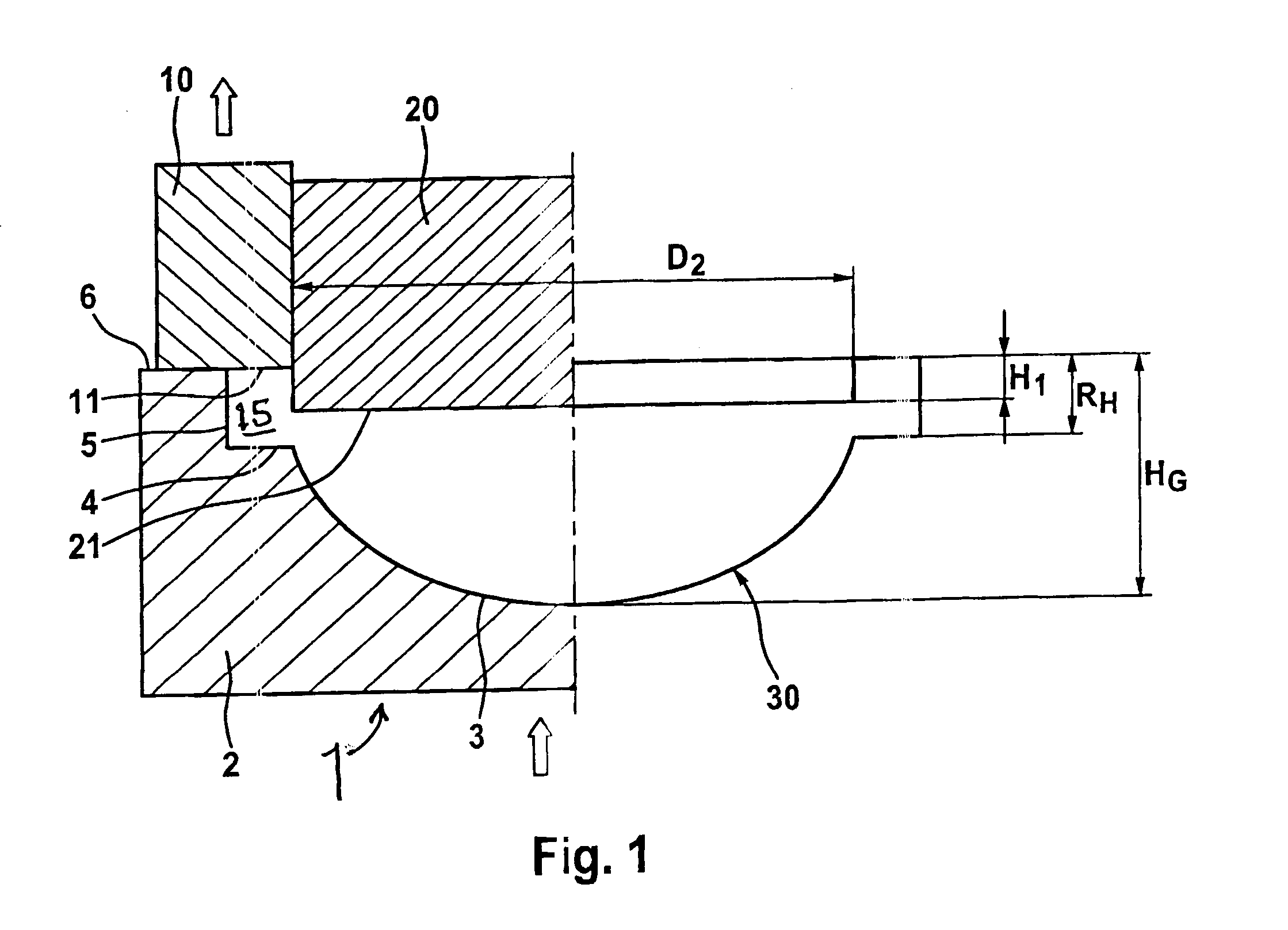
[0050] A precise pressing apparatus 1 is shown in cross-section on the left side of FIG. 1. This precise pressing apparatus comprises a lower mold part 2, an upper mold part 10, and a press die 20 of a diameter D2. A piano-convex lens 30 is made with this precise pressing apparatus 1, which can be used for a motor vehicle projection headlight.

[0051] The lower mold part 2 has an aspheric concave basin 3, a circumferential horizontal shoulder 4 extending around the concave basin and a vertical peripheral rim 5 extending up from the horizontal shoulder 4. The upper mold part 10 comprises a mold ring that bears on the facing surface 6 of the lower mold part 2 and that extends inward over and near the horizontal shoulder 4. The distance between the horizontal shoulder 4 and the underside of the mold ring defines the height RH of the supporting rim 34 of the lens 30.

[0052] In order to guarantee the optical properties of the lens 30 and to avoid tilting of the optic axis from the top sid...


PUM

PropertyMeasurementUnit
diameteraaaaaaaaaa
weightaaaaaaaaaa
diameteraaaaaaaaaa

Abstract

The method for making a lens with a first convex lens surface (32) and a second lens surface (33) includes feeding a glass melt drop into a concave mold (2, 10), precise pressing both sides of the glass melt drop in the concave mold (2, 10) together with a press die (20) and immersing the press die (20) in the glass melt drop so that a supporting rim (34) with predetermined dimensions, which protrudes beyond a highest point of the second lens surface (33), is formed on the lens by glass material displaced by the precise pressing. The apparatus for precise pressing includes an upper mold part (10) a lower mold part (2) and the press die (20).

Description

BACKGROUND OF THE INVENTION [0001] 1. Field of the Invention [0002] The present invention relates to a method of making a lens with a first convex lens surface and a second lens surface, especially for a motor vehicle headlight, in which a glass melt drop is supplied to a concave mold and both sides of the glass melt drop in the mold are precise pressed together with a press die. The invention also relates to an apparatus or tool for precise pressing both sides of the lens. [0003] 2. Related Art [0004] Many lenses, especially those for motor vehicle headlights, do not need to fulfill the highest specifications, like those for objectives in optical lenses. On the other hand, the dimensions of the lenses that must be taken into account for the assembly must not vary. Furthermore the lenses must be economical to manufacture. [0005] Usually those lenses are made by a single-side precise pressing method, i.e. a blank is heated, the aspheric side is pressed and the flat or planar side is ...

Claims


Application Information

Patent Timeline
Patent Type & Authority Applications(United States)
IPC IPC(8): G02B3/00
CPCC03B11/08F21S48/125C03B2215/49F21S41/25B29D11/00
Inventor BONITZ, RALFADEBAHR, RAINERPETERS, FRANK
Owner DOCTER OPTICS SE
Learn More