Backlight module

a backlight module and backlight technology, applied in the field of plane light sources, can solve the problems of inability to reduce the manufacturing cost of white light emitting diodes b>280/b>′, the display of cathode ray tubes (crts) is still marred by their bulky size, and the driving method of the backlight module is more complicated, so as to achieve the effect of convenient fabrication

Inactive Publication Date: 2006-04-06
DELTA ELECTRONICS INC
View PDF0 Cites 126 Cited by
  • Summary
  • Abstract
  • Description
  • Claims
  • Application Information

AI Technical Summary

Benefits of technology

[0041] The present invention disposes the fluorescence material on the transmission path of the first light emitted from the light emitting diode, or within the light guide plate, using the first light with a shorter wavelength to excite the fluorescence material to emit the second light with a longer wavelength. The first light and the second light are uniformly mixed to generate white light with a desired color temperature. In addition, the present invention can also use the first light with a shorter wavelength to exci...

Problems solved by technology

Though having some advantages, cathode ray tube (CRT) displays are still marred by their bulky size due to the electronic cavity structures and radiation generated during display.
As a result, the manufacturing costs of the white light emitting diode 280′ cannot be real...

Method used


Image

  • Backlight module
  • Backlight module
  • Backlight module

Examples


first embodiment

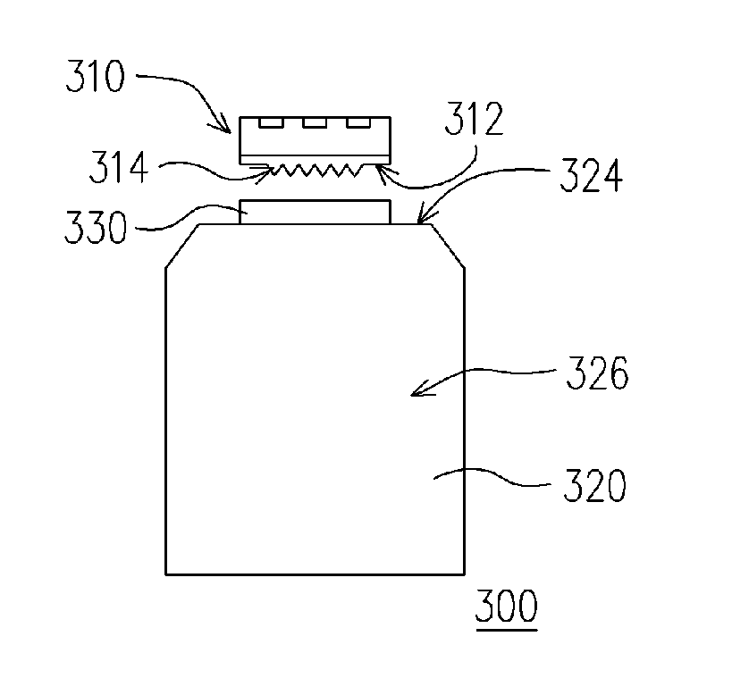
[0060]FIGS. 5 and 6 are a top view and a side view of a backlight module according to the first embodiment of the present invention. Referring to FIGS. 5 and 6, the backlight module 300 of this embodiment comprises a light emitting diode 310, a light guide plate 320 and a fluorescence material 330. Wherein, the light emitting diode 310 is adapted to emit a first light. The light emitting diode 310 comprises a first light-emitting surface 312, and a first light-diffusion surface 314 is located over the first light-emitting surface 312. The light guide plate 320 is disposed adjacent to the light emitting diode 310. The fluorescence material 330 is disposed between the light emitting diode 310 and the light guide plate 320, and on the transmission path of the first light. Wherein, after the first light-diffusion surface 314 diffuses the first light, the fluorescence material 330 is excited by the first light and emits a second light. Note that the shape of the first light-diffusion sur...

second embodiment

[0063]FIGS. 7 and 8 are a top view and a side view of a backlight module according to the second embodiment of the present invention. Referring to FIGS. 7 and 8, the backlight module 400 of this embodiment comprises a light emitting diode 410, a light guide plate 420 and plural fluorescence materials 430. Wherein, the light emitting diode 410 is adapted to emit a first light. The light emitting diode 410 comprises a first light-emitting surface 412, and a first light-diffusion surface 414 is located over the first light-emitting surface 412. The light guide plate 420 is disposed adjacent to the light emitting diode 410. The fluorescence materials 430 are disposed between the light emitting diode 410 and the light guide plate 420, and on the transmission path of the first light. Wherein, after the first light-diffusion surface 414 diffuses the first light, the fluorescence material 430 is excited by the first light and emits a second light. Note that the shape of the first light-diff...

third embodiment

[0067]FIGS. 11A-11C are top views of backlight modules according to the third embodiment of the present invention. Referring to FIG. 11A, the light guide plate 520 of the present invention comprises, for example, a second light-diffusion surface 523 over the light-incident surface 522a. In addition, the fluorescence material 530 is coated over the second diffusion surface 523 of the light guide plate 520, for example. Due to the toothed type structure of the second light-diffusion surface 523 of the light guide plate 520 shown in FIG. 11A, or the other types of surface capable of diffusing light, the light-mixing effect of the light guide plate 520 can be improved. In addition, the second light-diffusion surface 523 of the light guide plate 520 can enhance the adhesion between the fluorescence material 530 and the light guide plate 520.

[0068] Referring to FIG. 11B, the light guide plate 520 of this embodiment may comprise a concave 524 over the light-incident surface 522a, and the ...


PUM


Abstract

A backlight module is provided, comprising a light emitting diode (LED), a light guide plate and a fluorescence material. The fluorescence material is disposed in a transmission path of a first light or within the light guide plate. Then the fluorescence material is excited by the first light to generate one or more second lights. The first light and the second light are mixed or the second lights with different wavelengths are mixed to form a white light to generate a plane light source with a desired color temperature.

Description

CROSS-REFERENCE TO RELATED APPLICATION [0001] This application claims the priority benefit of Taiwan application serial no. 93129778, filed on Oct. 1, 2004. All disclosure of the Taiwan application is incorporated herein by reference. BACKGROUND OF THE INVENTION [0002] 1. Field of the Invention [0003] The present invention relates to a plane light source, and more particularly to a backlight module. [0004] 2. Description of the Related Art [0005] With the progress of computer, internet and multi-media technology, image data transmission has advanced to digital transmission, rather than analog transmission. In order to fit the modern life style, visual or image apparatus has become thinner and lighter. Though having some advantages, cathode ray tube (CRT) displays are still marred by their bulky size due to the electronic cavity structures and radiation generated during display. Accordingly, combining opto-electronic technology and semiconductor technology, flat plane displays (FPDs)...

Claims


Application Information

Patent Timeline
IPC IPC(8): F21V7/04H01L33/50
CPCG02B6/0013G02B6/002G02B6/0025G02B6/0026G02B6/0031G02B6/005
Inventor LI, HSIAO-ICHENG, HUNG-LUNGHUANG, KENNYHSIEH, MEI-LUANWENG, CHIA-CHENGHUANG, CHIH-HENGLIU, HO-CHIANG
Owner DELTA ELECTRONICS INC
Why Eureka
Try Eureka