
Multi-zone atomic layer deposition apparatus and method

a technology of atomic layer and deposition apparatus, which is applied in the direction of chemical vapor deposition coating, metal material coating process, coating, etc., can solve the problems of affecting the deposition rate of atomic particles on the substrate, and achieve the effect of high deposition rate and high quality

Inactive Publication Date: 2006-04-06
ATOMICITY SYST
View PDF31 Cites 163 Cited by
  • Summary
  • Abstract
  • Description
  • Claims
  • Application Information

AI Technical Summary

Benefits of technology

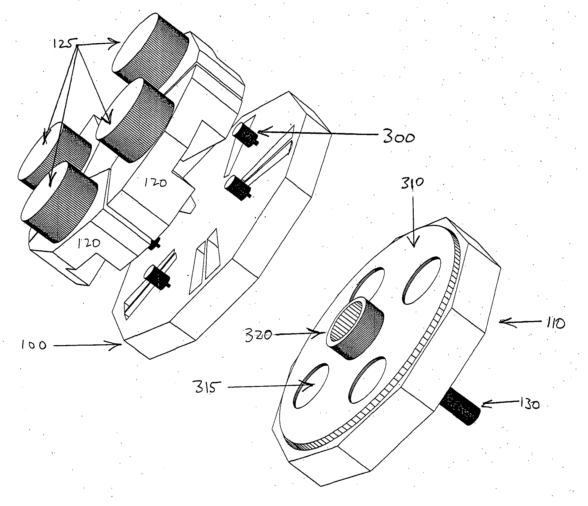
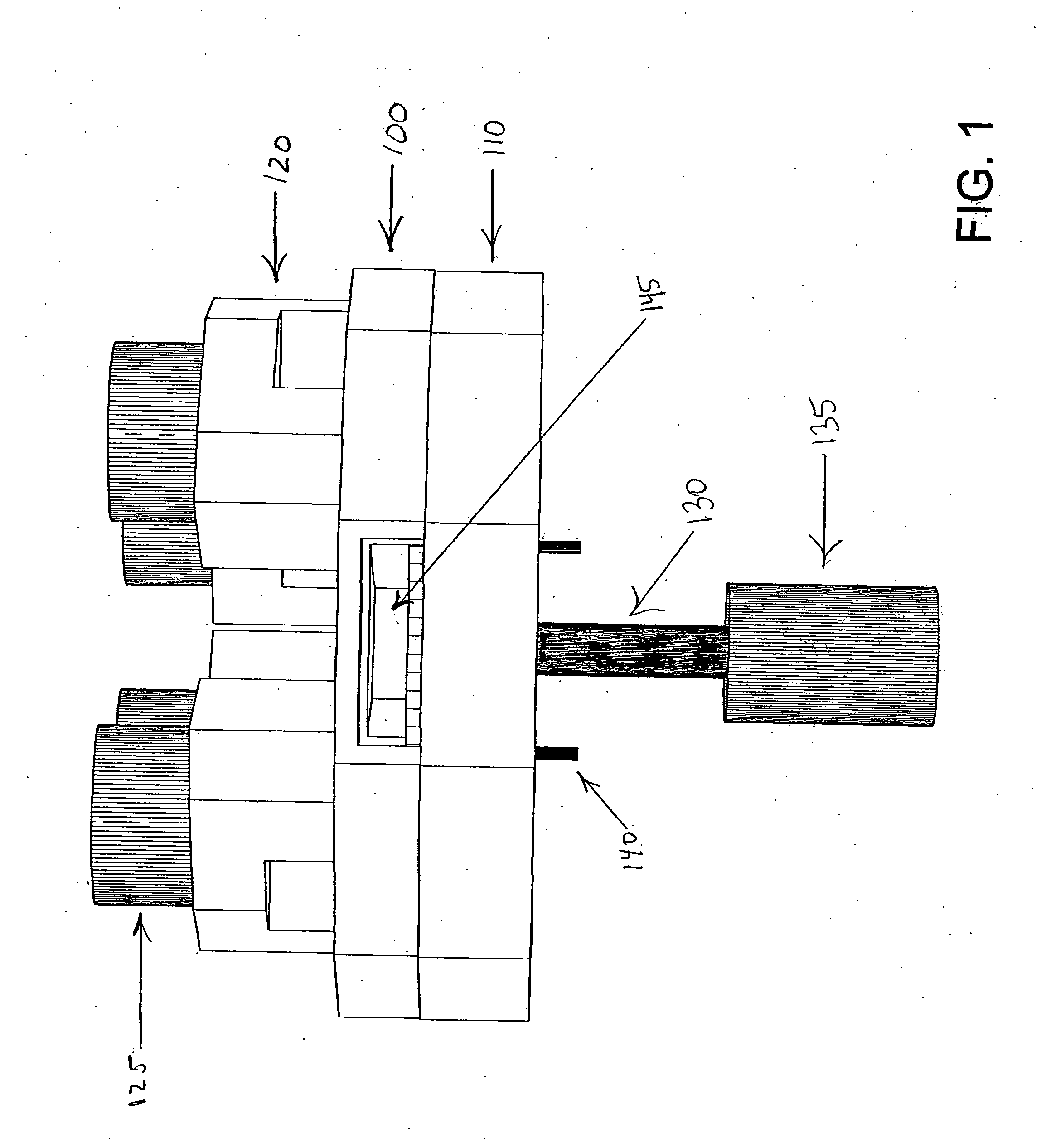
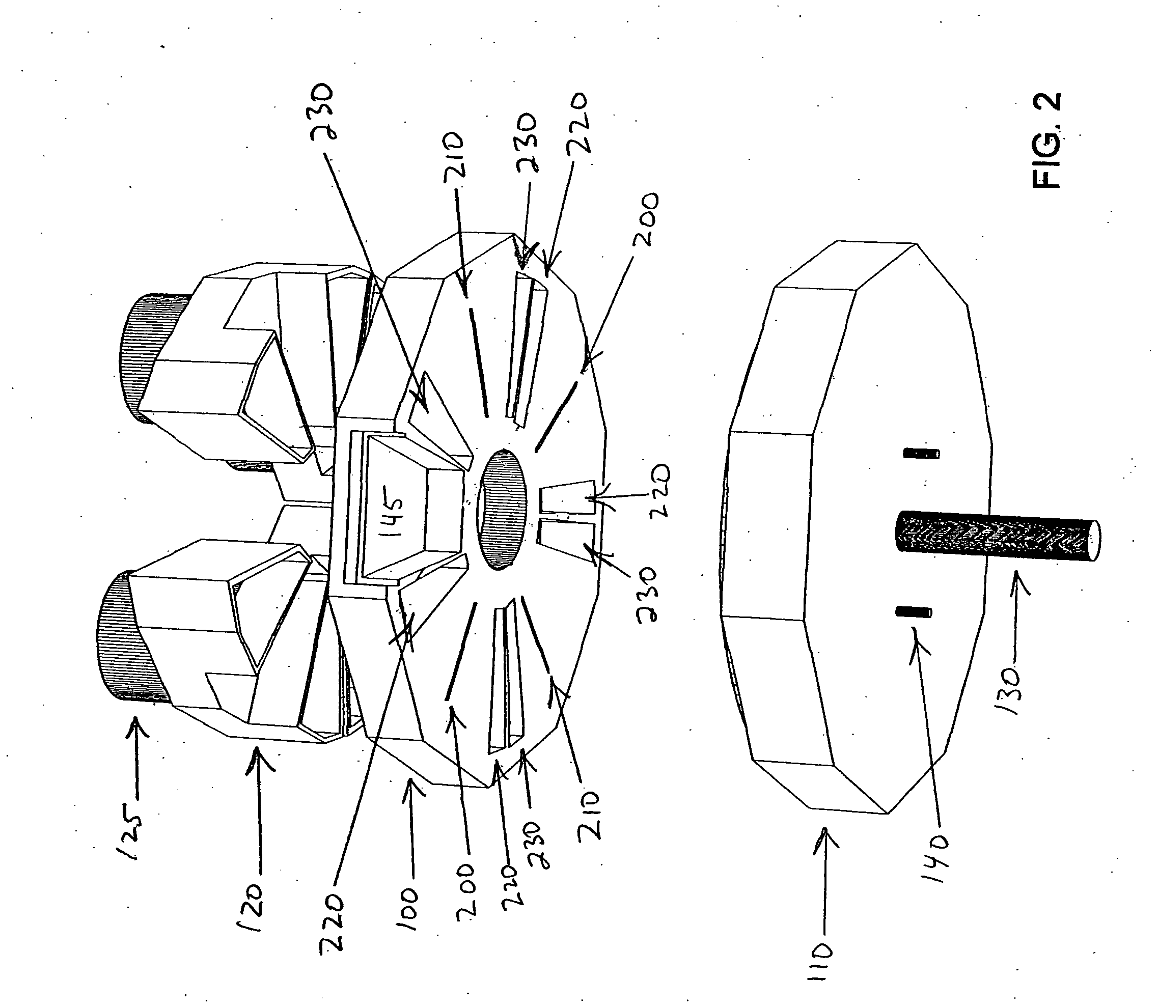
[0013] In one aspect, the present invention overcomes the limitations of the prior art by employing a series of dedicated low volume precursor deposition zones separated by dedicated larger volume exhaust zones, in conjunction with a moving substrate holder disposed within a chamber. The internal chamber walls and the substrate holder form a small gap that acts to provide for the passage of a given precursor gas across a substrate in a given dedicated deposition zone but restricts the flow of different precursor(s) and / or reaction by-products from the given deposition zone into another dedicated zone. Typically, the system is not internally leak proof but a high degree of precursor separation is achieved, resulting in a platform that is able to produce high quality ALD films at high deposition rates.
[0014] Deposition zones are created when the substrate is moved by the substrate holder into a precursor inlet zone and precursor gas is injected such that it flows across the substrate toward the dedicated larger volume exhaust zones. Because the deposition zone for a given precursor inlet zone is dedicated, i.e., only one precursor is explicitly introduced, there is no longer a need to remove excess precursor from the zone. Because the exhaust zones have large volume, excess precursor and reaction by-products have very low pressure in the exhaust zone as the substrate moves to the deposition zone for the next precursor gas. Very little precursor gas from one precursor region is able to reach another precursor region because of the low precursor / by-products pressure, efficient exhausting, as well as the flow restrictions imposed by the gap, disk hub, etc. This approach eliminates the need for an explicit purge of a precursor from the deposition zone, thus improving the cycle rate. However, purges in between the adjacent exhaust zones can be used to act as an additional diffusion barrier limiting a given precursor flow to within its dedicated deposition and exhaust zone. The use of high speed valves, now commercially available, in supplying timed injections of precursor gases and purge gases improve the overall gas management, cleanliness, and speed of the system. Substrate cleanliness is further enhanced by the fact that pressures typically are maintained below order 1 torr even at the precursor inlet zone such that particle movement does not readily take place. In the case of explicit purges between exhaust zones, higher pressures may be encountered resulting in possible deleterious particle movement onto the substrate if the chamber and / or substrate are inadequately clean.
[0015] Various aspects of the invention include the following. The precursor reactants preferably are separated (via the use of dedicated precursor deposition zones) except where they are supposed to react, namely at the surface of the substrate. The use of low volume, dedicated deposition zones leads to efficiency, cleanliness, and speed improvements. The pulsing of gases into the relatively low pressure system limits the amount of gas introduced into the system and the gas moves rapidly to where it needs to be. As a final example, the use of large exhaust volumes with high gas conductance and high pumping rates results in effective removal of excess precursor and reaction by-products.

Problems solved by technology

In the case of explicit purges between exhaust zones, higher pressures may be encountered resulting in possible deleterious particle movement onto the substrate if the chamber and / or substrate are inadequately clean.

Method used


Image

  • Multi-zone atomic layer deposition apparatus and method
  • Multi-zone atomic layer deposition apparatus and method
  • Multi-zone atomic layer deposition apparatus and method

Examples


Embodiment Construction

[0037] Before moving on to specific embodiments, a few comments about the conventional ALD process and apparatus are in order. A complete conventional cycle typically requires four steps to produce a monolayer. First, a first precursor gas is introduced into the reactor chamber and adsorbs onto a substrate. Second, the excess first precursor gas is then purged from the reactor chamber. Third, a second precursor gas is introduced into the reactor chamber and reacts with the first adsorbed precursor. Finally, the reaction by-products and the excess second precursor gas is purged from the reactor chamber leaving behind the desired layer on the substrate. This process is repeated to grow a layer of desired thickness. In fact, the first several cycles typically do not result in a uniform layer across the substrate as some substrate sites grow preferentially but eventually the surface is covered and growth continues across the entire surface. An important consideration is that the tempera...


PUM

PropertyMeasurementUnit
Lengthaaaaaaaaaa
Lengthaaaaaaaaaa
Lengthaaaaaaaaaa

Abstract

Method and apparatus for producing a thin film on a substrate set in a moving substrate holder is disclosed. Within a deposition chamber, a substrate is moved across a series of dedicated deposition zones and is subjected to repeated surface reactions with at least two different reactants. The reactants are fed into the dedicated deposition zones from a gas supply system that may include high speed valves that are timed to coordinate with the passage of the substrate so as to inject reactive gases repeatedly into the deposition zones. The dedicated deposition zones are separated by dedicated exhaust zones that direct each reactive gas along separate paths so as to minimize or eliminate mixing of different reactive species in the exhaust thus decreasing deposition within the exhaust system.

Description

CROSS-REFERENCE TO RELATED APPLICATION [0001] This application claims priority under 35 U.S.C. § 119(e) to U.S. Provisional Patent Application Ser. No. 60 / 616,167, “Multi-Zone Atomic Layer Deposition Apparatus and Method,” filed Oct. 4, 2004, which is incorporated herein by reference in its entirety.BACKGROUND OF THE INVENTION [0002] 1. Field of the Invention [0003] This invention relates generally to thin film deposition apparatus and methods. More particularly, it relates to atomic layer deposition apparatus and methods. [0004] 2. Description of the Related Art [0005] Thin films are generally deposited on semiconductor substrates by a physical vapor deposition (PVD) process such as sputtering or by a chemical vapor deposition (CVD) process. However, when the surface of the substrate is strongly stepped (e.g., high aspect ratio structures that are narrow and deep) and the dimension of the opening at the top of the structure is small, as can occur in current day semiconductor design...

Claims


Application Information

Patent Timeline
IPC IPC(8): C23C16/00
CPCC23C16/4412C23C16/45525C23C16/45551
Inventor ANTONISSEN, ERIC
Owner ATOMICITY SYST
Learn More