Apparatus and test device for the application and measurement of prescribed, predicted and controlled contact pressure on wires

a test device and wire technology, applied in the direction of lighting and heating apparatus, instruments, and semiconductor/solid-state device details, can solve the problems of inability to create viable and functionally reliable products, difficult to achieve the effect of achieving effective control of contact pressure, and significant restrictions on how to achieve them

Active Publication Date: 2006-04-06
SAMSUNG ELECTRONICS CO LTD
View PDF6 Cites 74 Cited by
  • Summary
  • Abstract
  • Description
  • Claims
  • Application Information

AI Technical Summary

Benefits of technology

[0010] The mechanical behavior of wires subjected to axial loading and experiencing bending deformation is used to ensure effective control of the contact pressure in mechanical and / or heat removing devices, and similar structures and systems. An apparatus for taking advantage of the characteristics of wires in packaging of a device, such as a semiconductor device, is disclosed, as well as a test device for identifying the accurate contact pressure required in same. Methods for the prediction of such a behavior in the pre-buckling, buckling, and post-buckling conditions in wires, carbon nanotubes (CNTs), and similar wire-grid-array (WGA) structures are also disclosed.

Problems solved by technology

This requirement often imposes significant restrictions on, and difficulties in, how the wire-grid-array (WGA) is designed, manufactured, and operated.
In some applications, such as, CNT-based advanced heat-sinks, it is practically impossible to create a viable and functionally reliable product, if effective and insightful predictive modeling, preferably based on an analytical approach, is introduced and carried out prior to actual design and manufacturing efforts.
Prior art solutions suffer from several deficiencies.
Notably, several mechanical and physical design problems arise in connection with such an application, including: a) Insufficient anchoring strength of the root portion of the rods, including weak adhesion to the base; and b) Extraordinary variability of the diameters and lengths of the grown wires and, because of that, a significant variability and even uncertainty in the produced contact pressure.

Method used


Image

  • Apparatus and test device for the application and measurement of prescribed, predicted and controlled contact pressure on wires
  • Apparatus and test device for the application and measurement of prescribed, predicted and controlled contact pressure on wires
  • Apparatus and test device for the application and measurement of prescribed, predicted and controlled contact pressure on wires

Examples


Embodiment Construction

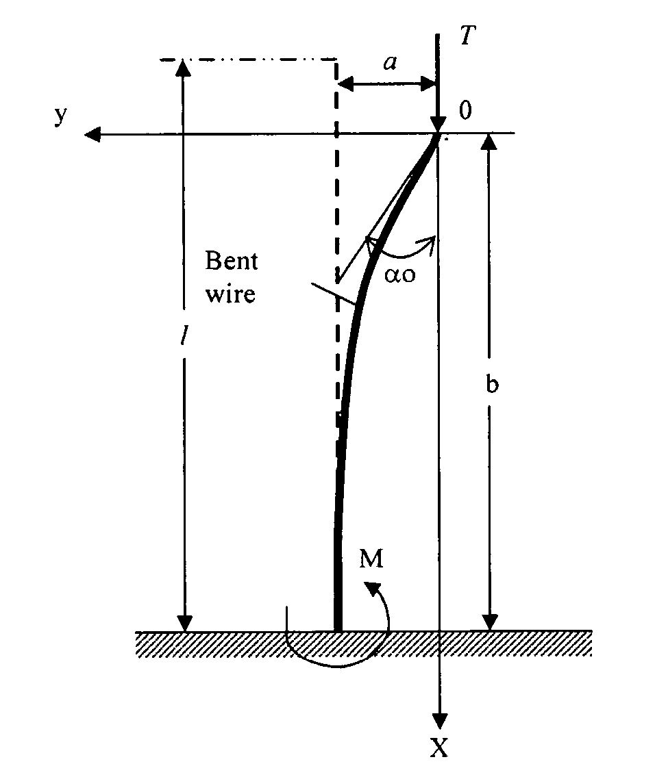
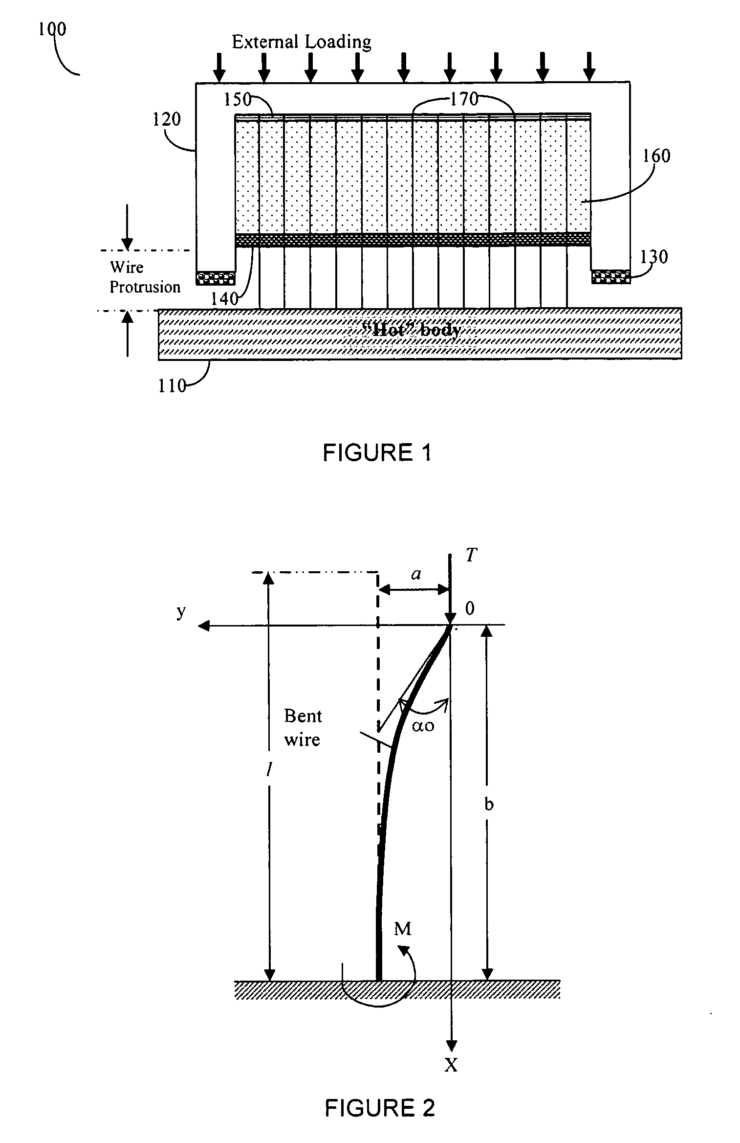
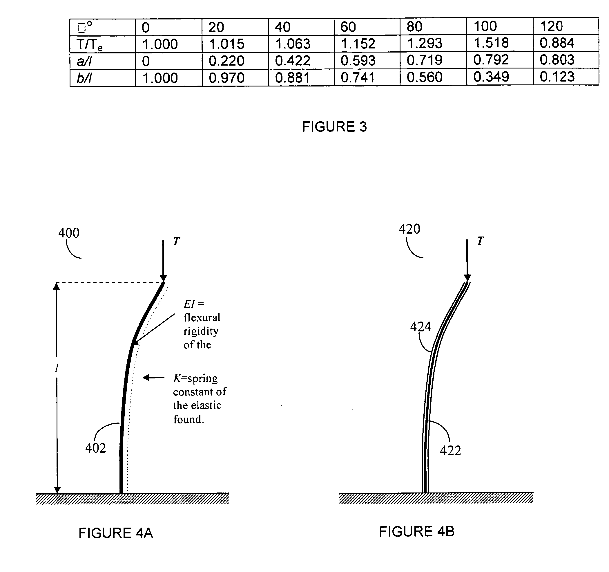
[0021] The invention disclosed herein uses the phenomena of bending and the elastic stability or instability of rods, whether free-span, i.e. un-embedded into any elastic or inelastic continuous medium, rods, or those that can be idealized as beams lying on continuous foundations. In accordance with one embodiment of the invention, these phenomena are used to provide and control the required contact pressure for a wire-grid-array (WGA). A key objective of the invention is to develop a WGA design that is least sensitive to the inevitable variations in materials' properties and wire (“beam”) geometries (diameters, lengths, prismaticity, etc.). The WGA may comprise of, but not limited to, a plurality of rods, which include, but are not limited to, nano-rods, nano-wires, carbon nanotubes (CNT), optical fibers, carbon nano-fibers, Gecko type “hair”, Velcro-type elements, and the like. For the purpose of this disclosure, the terms wire(s) or rod(s) are used interchangeably to indicate, wi...


PUM


Abstract

The mechanical behavior of wires subjected to axial loading and experiencing bending deformation is used to ensure effective control of the contact pressure in mechanical and/or heat removing devices, and similar structures and systems. An apparatus for taking advantage of the characteristics of wires in packaging of a device, such as a semiconductor device, is disclosed, as well as a test device for identifying the accurate contact pressure required in same. Methods for the prediction of such a behavior for pre-buckling, buckling, and post-buckling conditions in wires, carbon nanotubes (CNTs), and similar wire-grid-array (WGA) structures, for example are also disclosed.

Description

CROSS REFERENCE TO RELATED APPLICATION [0001] This application claims the benefit of U.S. provisional patent application No. 60 / 615,601 filed Oct. 5, 2004, which application is incorporated herein in its entirety by the reference theretoBACKGROUND OF THE INVENTION [0002] 1. Field of the Invention [0003] The invention pertains generally to an apparatus and method for device design, prediction of its mechanical behavior and passive control of contact pressure using the phenomena of bending of wires subjected to axial loading, including the phenomenon of elastic stability, and with a particular emphasis on mechanical, electrical, optical, and heat removing devices. [0004] 2. Description of the Prior Art [0005] The performance of many mechanical, electrical, optical and thermal devices is sensitive to the level of, and the changes in, contact pressure. For example, a flexible (“Euler”, “Cobra”, buckled beam) electrical test probe provides an attractive solution to making electrical cont...

Claims


Application Information

Patent Timeline
Patent Type & Authority Applications(United States)
IPC IPC(8): H01R12/00
CPCB82Y10/00G01R1/06716G01R1/07357G01R1/0675H01L2224/73253H01L2924/01079H01L2924/01019G01R1/44H01L23/373
Inventor SUHIR, EPHRAIM
Owner SAMSUNG ELECTRONICS CO LTD
Why Eureka
Try Eureka