Operating voltage determination for an integrated circuit

a technology of operating voltage and integrated circuit, which is applied in the direction of information storage, liquid/fluent solid measurement, sustainable buildings, etc., can solve the problem that the given integrated circuit may not be able to reliably operate at the intended clocking frequency for a given supply voltage, and achieves more time-efficient testing process, reduces the likelihood of failure of the integrated circuit, and more efficient energy use.

Active Publication Date: 2006-04-06
ARM LTD
View PDF4 Cites 52 Cited by
  • Summary
  • Abstract
  • Description
  • Claims
  • Application Information

AI Technical Summary

Benefits of technology

[0011] The present invention recognises that rather than categorising groups of integrated circuits according to the highest frequencies that they can reliably support at a given supply voltage, individual integrated circuits may be categorised according to the lowest voltage that is required to reliably sustain a required operating frequency. This means that variations in the integrated circuit fabrication, such variations as doping levels, can be taken into account on a circuit by circuit basis by actively testing the lowest voltage that an individual integrated circuit can sustain in order to reliably operate at the required frequency. This means that, unlike known frequency binning techniques, there is no need to build in substantial margins into the specified operating voltage (effectively increasing the operating voltage significantly above the required minimum voltage) to account for variations in the fabrication process. Accordingly, on a specific integrated circuit the operating voltage determined according to the present technique may be lowered by hundreds of millivolts with regard to the operating voltage determined for the corresponding group of frequency binned integrated circuits. Running at a lower operating voltage makes more efficient use of available energy.
[0025] Although the operational voltage determination could be performed only on boot up or during normal operation of the end device, in preferred embodiments operational voltage determination is initiated when the integrated circuit within the end device is in a standby state to identify a body bias voltage that results in a lowest leakage current for a current charge level of the battery. This provides a mechanism for reducing power consumption in standby mode thereby prolonging battery lifetime.

Problems solved by technology

As a consequence of manufacturing tolerances within integrated circuits, a given integrated circuit may not be capable of operating reliably at the intended clocking frequency for a given supply voltage.

Method used


Image

  • Operating voltage determination for an integrated circuit
  • Operating voltage determination for an integrated circuit
  • Operating voltage determination for an integrated circuit

Examples


Embodiment Construction

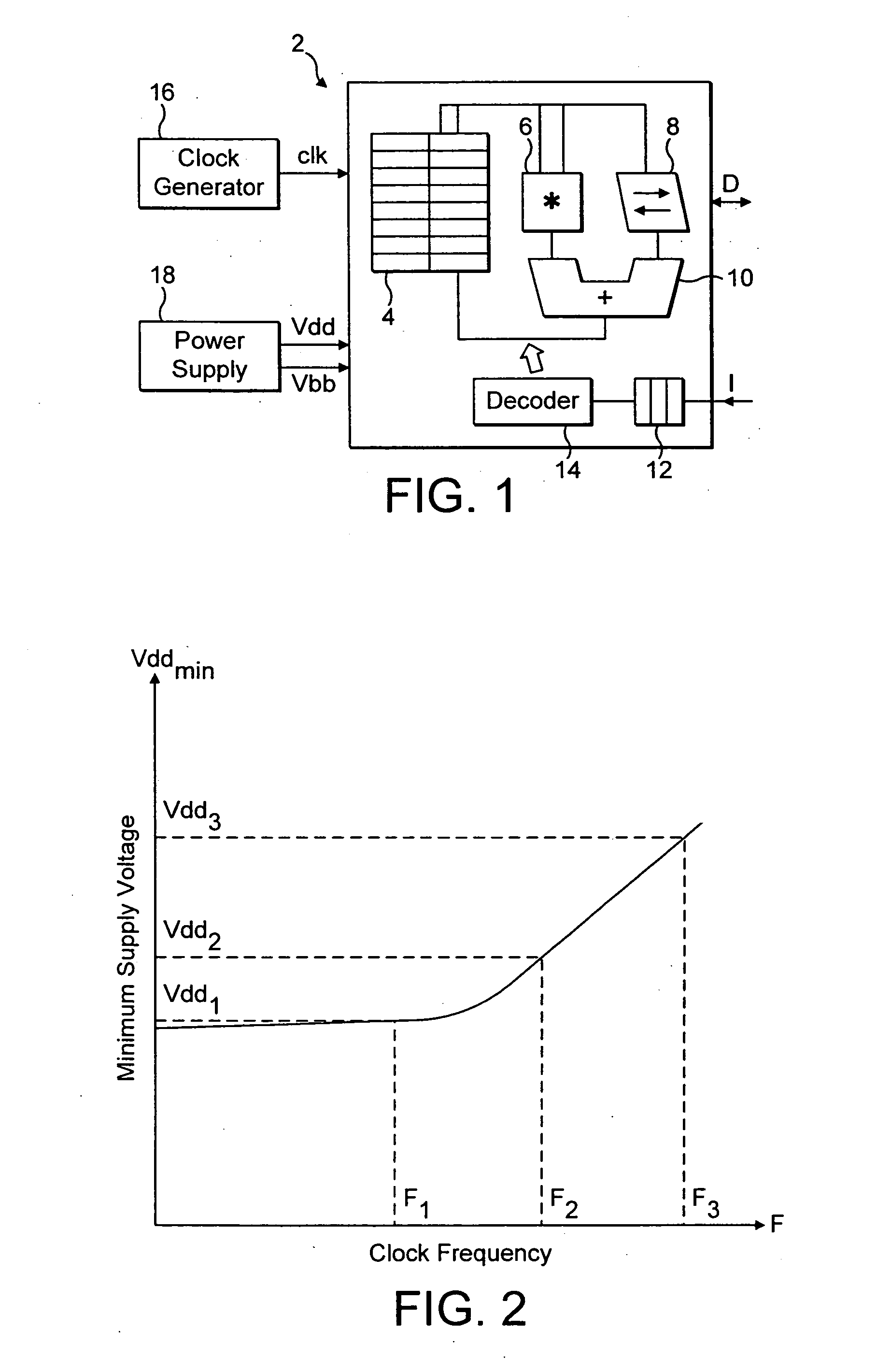
[0048]FIG. 1 illustrates an integrated circuit 2 in the form of a processor core incorporating a register bank 4, a multiplier 6, a shifter 8, an adder 10, an instruction pipeline 12 and an instruction decoder 14. In operation program instructions received into the instruction pipeline 12 are decoded by the instruction decoder 14 which generates control signals for controlling the operation of the register bank 4, the multiplier 6, the shifter 8 and the adder 10 as well as further circuit elements (not illustrated) to perform data processing operations specified by the program instructions.

[0049] The integrated circuit 2 is supplied by a processor clock signal clk generated by a clock generator 16. This clock signal clk can have different frequencies, these frequencies being dynamically altered depending upon the performance required of the integrated circuit 2 at a particular point in time. As an example, if the integrated circuit 2 is required to perform a processing intensive ta...


PUM


Abstract

Voltage-binning of individual integrated circuits is achieved by operating those integrated circuits at a plurality of required clock frequencies and for each of those frequencies determining the minimum supply voltage level which produces a pass result for a series of applied test vectors.

Description

BACKGROUND OF THE INVENTION [0001] 1. Field of the Invention [0002] This invention relates to the field of integrated circuits. More particularly, this invention relates to the determination of operating voltages for integrated circuits. [0003] 2. Description of the Prior Art [0004] In the field of integrated circuits there is a drive to increase processing performance by running integrated circuits at progressively higher clocking frequencies. As a consequence of manufacturing tolerances within integrated circuits, a given integrated circuit may not be capable of operating reliably at the intended clocking frequency for a given supply voltage. Accordingly, at the production stage following fabrication, each integrated circuit is tested at a range of test frequencies to determine the highest operating frequency that it can support at the given supply voltage. The integrated circuits are then categorised for use up to that highest operating frequency. [0005] There is also a drive in ...

Claims


Application Information

Patent Timeline
Patent Type & Authority Applications(United States)
IPC IPC(8): G01R19/00G06F1/06G06F1/08G06F1/24G06F1/26G06F1/32
CPCG01R31/3004G01R31/31718G06F1/26G06F1/3203G06F1/324G06F1/3296Y02B60/1217Y02B60/1285Y02D10/00G06F1/32
Inventor PATEL, DIPESH ISHWERBHAIFLAUTNER, KRISZTIAN
Owner ARM LTD
Why Eureka
Try Eureka