Focal plane antenna to sensor interface for an ultra-sensitive silicon sensor

Active Publication Date: 2006-04-13
NORTHROP GRUMMAN SYST CORP
View PDF4 Cites 27 Cited by
  • Summary
  • Abstract
  • Description
  • Claims
  • Application Information

AI Technical Summary

Benefits of technology

[0009] It is an object of the present invention to provide an electrical interface between a scene to be imaged, and a bolometer type sensor located, for example in a pixel, and wherein the efficiency of each pixel is improved by means of a thermal energy concentrator including a lens and an antenna. Where a plurality of pixels are located in an array, a microantenna is provided for each pixel in the array with a common lens b

Problems solved by technology

Extending these devices to other spectral band

Method used


Image

  • Focal plane antenna to sensor interface for an ultra-sensitive silicon sensor
  • Focal plane antenna to sensor interface for an ultra-sensitive silicon sensor
  • Focal plane antenna to sensor interface for an ultra-sensitive silicon sensor

Examples


Embodiment Construction

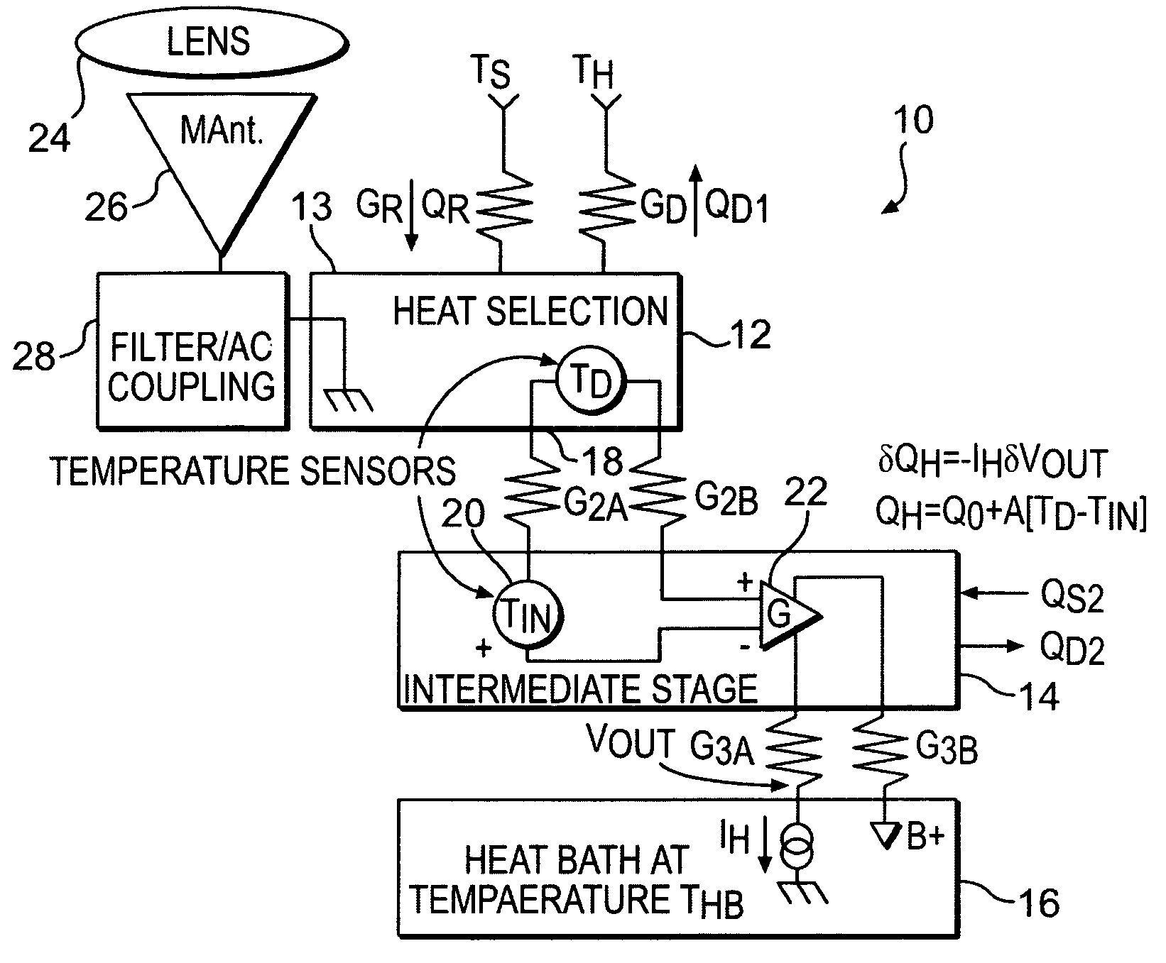
[0030] Referring now to the drawings wherein like reference numerals refer to like elements, reference is first made to FIG. 1. There, reference numeral 10 denotes an “ultra-sensitive” bolometer pixel including a detector stage 12, an intermediate stage 14, and a heat bath stage 16. Temperature sensors 18 and 20 are respectively located in the detector stage 12 and intermediate stage 14 and comprise silicon diodes connected in back-to-back relationship to an amplifier 22, also located in the intermediate stage 14. The amplifier generates heat in the intermediate stage 14 and electrothermal feedback zeroes the thermal difference between the heat detector stage and the intermediate stage.

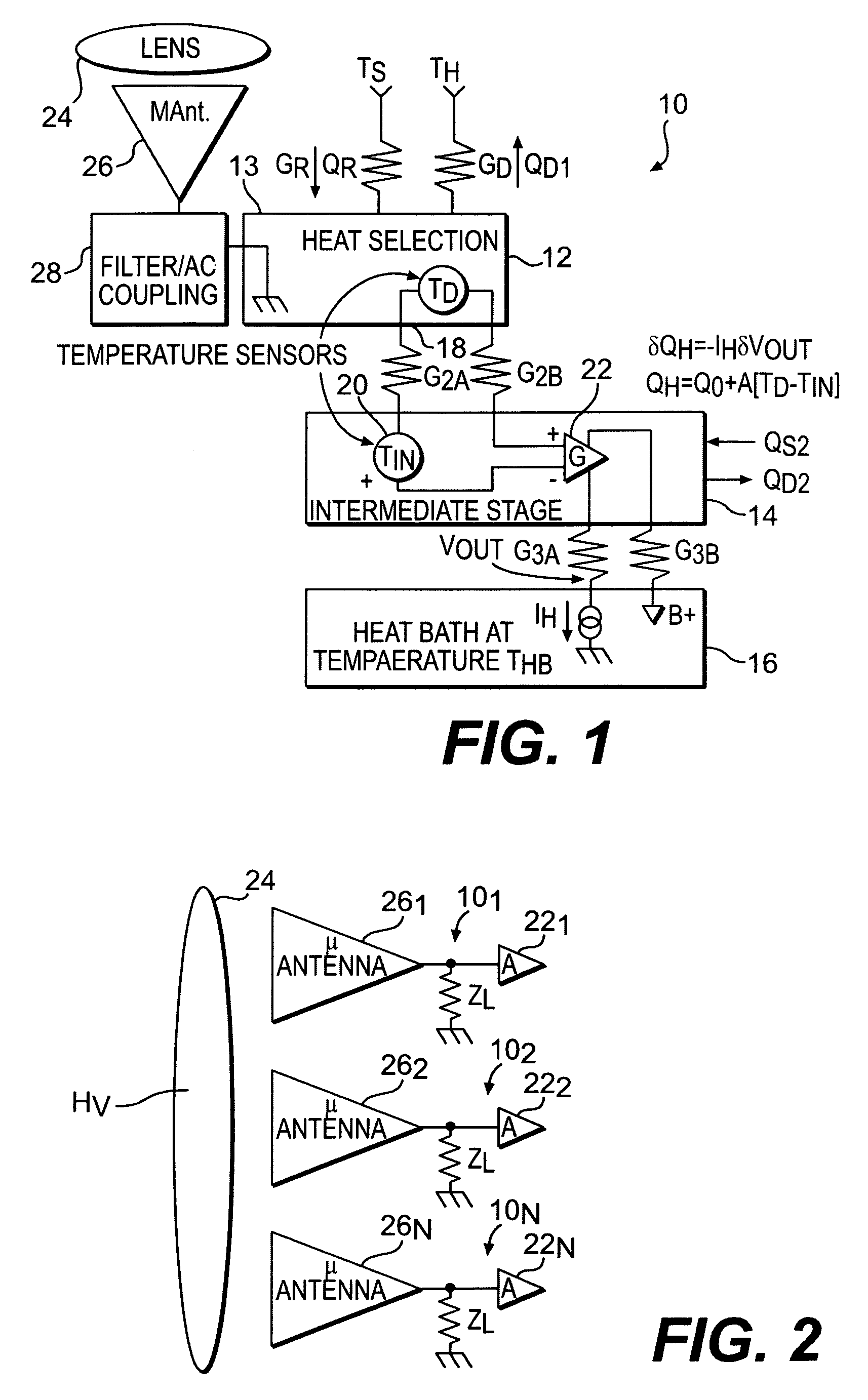
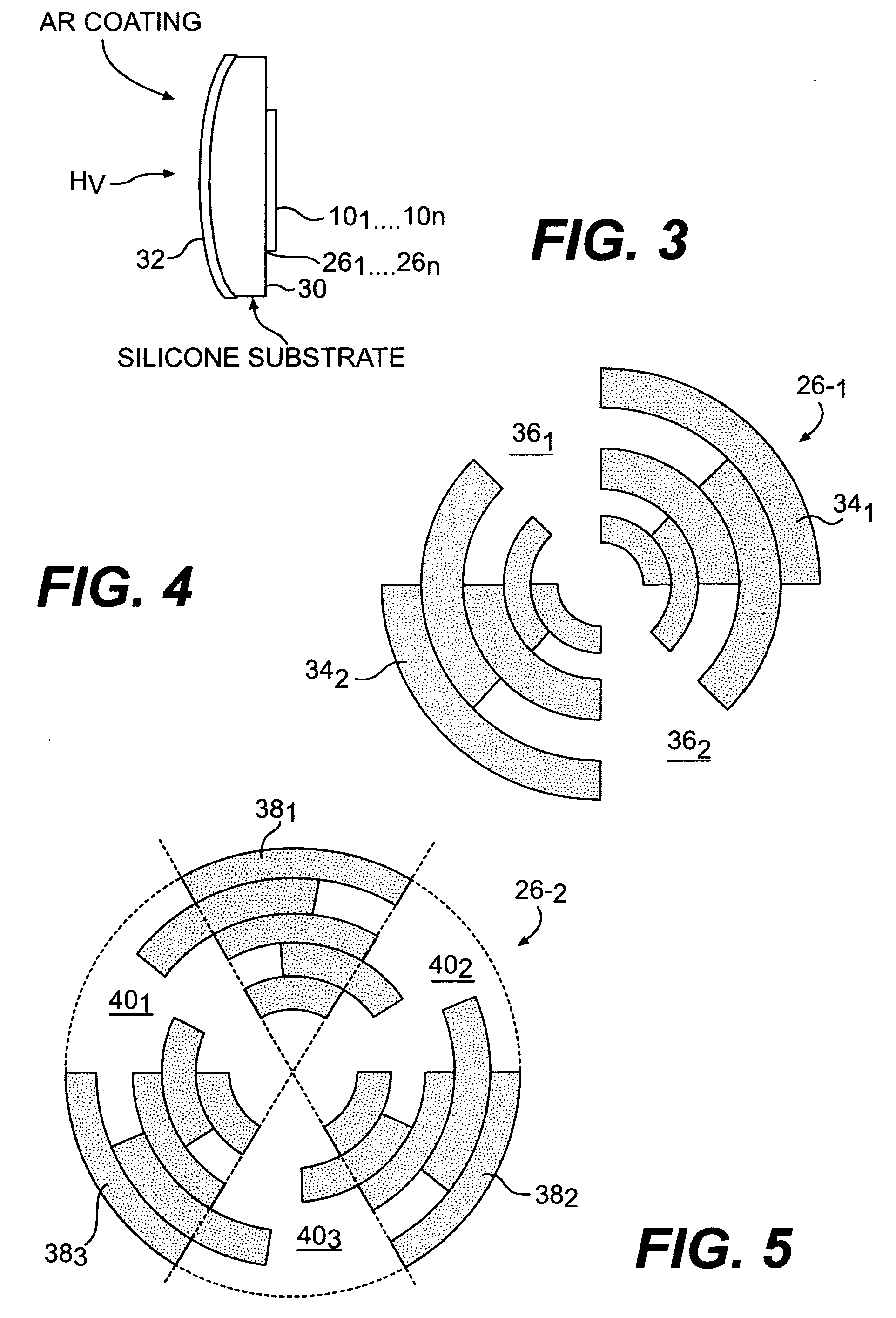
[0031]FIG. 1 also shows inclusion of a lens 24 which is utilized to focus thermal radiation from an external scene to an antenna structure 26 comprising an array of microantennas, two examples of which are further depicted in FIGS. 4 and 5. The microantenna 26 operates to channel received radiation t...


PUM


Abstract

An electrical interface between a scene to be imaged and a bolometer type sensor is disclosed. Efficiency is improved by means of a thermal energy concentrator including a lens and an antenna. Where a plurality of bolometer pixels are located in an array, a microantenna is provided for each pixel in the array with a common lens being provided to focus and channel incoming radiation to each microantenna. Radiation from a scene is further coupled by means of a lens and microantenna to the absorbing element of each bolometer through an AC coupling circuit including an electronic chopper implemented by means of a PIN diode, the conductivity of which is varied so as to affect the reflection coefficient of the input signal supplied through the microantenna.

Description

CLAIM OF PRIORITY [0001] This application is a Non-provisional application including the subject matter and claiming the priority date Under 35 U.S.C. §119(e) of Provisional application Ser. No. 60 / 614,472, filed Oct. 1, 2004, the contents of which are meant to be incorporated herein by reference. RELATED APPLICATIONS [0002] This application is related to Non-provisional application Ser. No. ______, (Northrop Grumman Ref. No. 000800-078) entitled “Sensitive Silicon Sensor And Test Structure For An Ultra-Sensitive Silicon Sensor” filed on ______, 2005, and U.S. Ser. No. ______, entitled “Ultra-Sensitive Silicon Sensor Readout Circuitry” (Northrop Grumman Ref.: No. 000776-078) filed on _____, 2005.BACKGROUND OF THE INVENTION [0003] 1. Field of the Invention [0004] This invention relates generally to bolometer type radiation sensors for detecting thermal radiation and more particularly to the interface circuitry between a silicon type bolometer sensor and the antenna means therefor. [0...

Claims


Application Information

Patent Timeline
IPC IPC(8): G01J5/00
CPCG01J5/08G01J5/0837G01J5/20G01J5/22G01J5/24G01K17/003
Inventor BLUZER, NATHAN
Owner NORTHROP GRUMMAN SYST CORP
Why Eureka
Try Eureka