Apparatus and method for seismic measurement-while-drilling

a technology of apparatus and method, applied in the field of apparatus and method for seismic measurementwhiledrilling, can solve the problems of noise, interference, attenuation, and surface seismic data cannot provide the velocity data that is required, and wireline seismic surveys typically require lengthy and expensive interruption of drilling process

Inactive Publication Date: 2006-04-13
NOVADRILL
View PDF12 Cites 73 Cited by
  • Summary
  • Abstract
  • Description
  • Claims
  • Application Information

AI Technical Summary

Benefits of technology

[0016] A tube wave suppression device may be positioned between the source and the receiver to eliminate or suppress tube waves that are guided along the borehole between the source and the receiver.

Problems solved by technology

An outstanding problem in the exploration for new hydrocarbons and in the development of known hydrocarbon reservoirs is determining the location of reflectors in subterranean formations.
This is the most widely-used type of geophysical survey, but it is hampered by noise, interference, and attenuation that occur near the surface.
However, surface seismic data cannot provide the velocity data that is required for the transformation of the subsurface seismic map from the time domain to the spatial domain.
Wireline seismic surveys typically require lengthy and expensive interruption of the drilling process.
A zone that is saturated with gas will attenuate the seismic waves, causing a seismic shadow.
The chief obstacle to widespread use of RVSP MWD is the difficulty in obtaining an accurate source pilot signal for correlation with the signals obtained by the surface receivers.
Provision of a source pilot signal at the top of the string is hindered by two difficulties.
First, the pilot signal from the source at the bottom of the drill string is highly attenuated, clipped, multiply reflected, and distorted during its long passage through the drill string.
Secondly, noise generated by rotation and vibration of the string itself can overwhelm the source signal.
Seismic processing methods that seek to eliminate the need for a direct source pilot signal require a strong and distinct direct wave, which is not always available.
RVSP MWD techniques that employ the drill bit as the source are generally limited to use of roller bits in hard formations, because shear bits, which are widely used in softer formations, generally do not provide a sufficient impulse for detection after being attenuated by poorly-consolidated near-surface formations.
Provision of a wireline for the pilot signal may interrupt the drilling process as severely as does a wireline seismic survey.
Accordingly, the deployment of receivers in the drill string for VSP MWD has generally been limited by the low bandwidth of existing downhole telemetry systems.
This enables transformation of the surface seismic model from the time domain to the spatial domain, but identification of approaching or receding reflectors can only be made after the tool is tripped out of hole—often too late to take corrective action.
The source wave will suffer high attenuation, distortion, surface-directed refraction, scattering from unknown surface reflectors, and interference from rig noise and cultural activities.
This can only be facilitated by a high-speed, real-time downhole data transmission system.

Method used


Image

  • Apparatus and method for seismic measurement-while-drilling
  • Apparatus and method for seismic measurement-while-drilling
  • Apparatus and method for seismic measurement-while-drilling

Examples


example 1

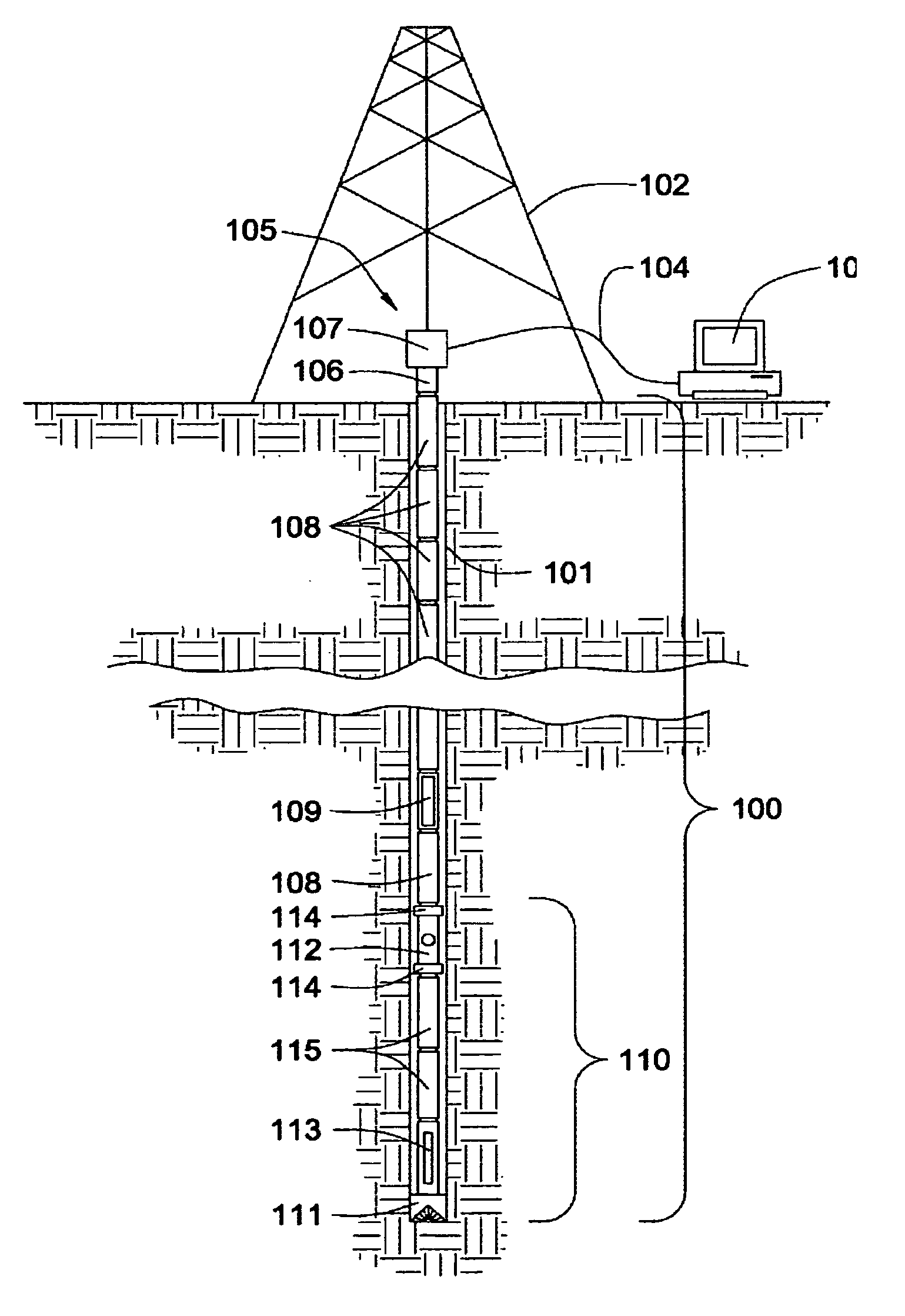
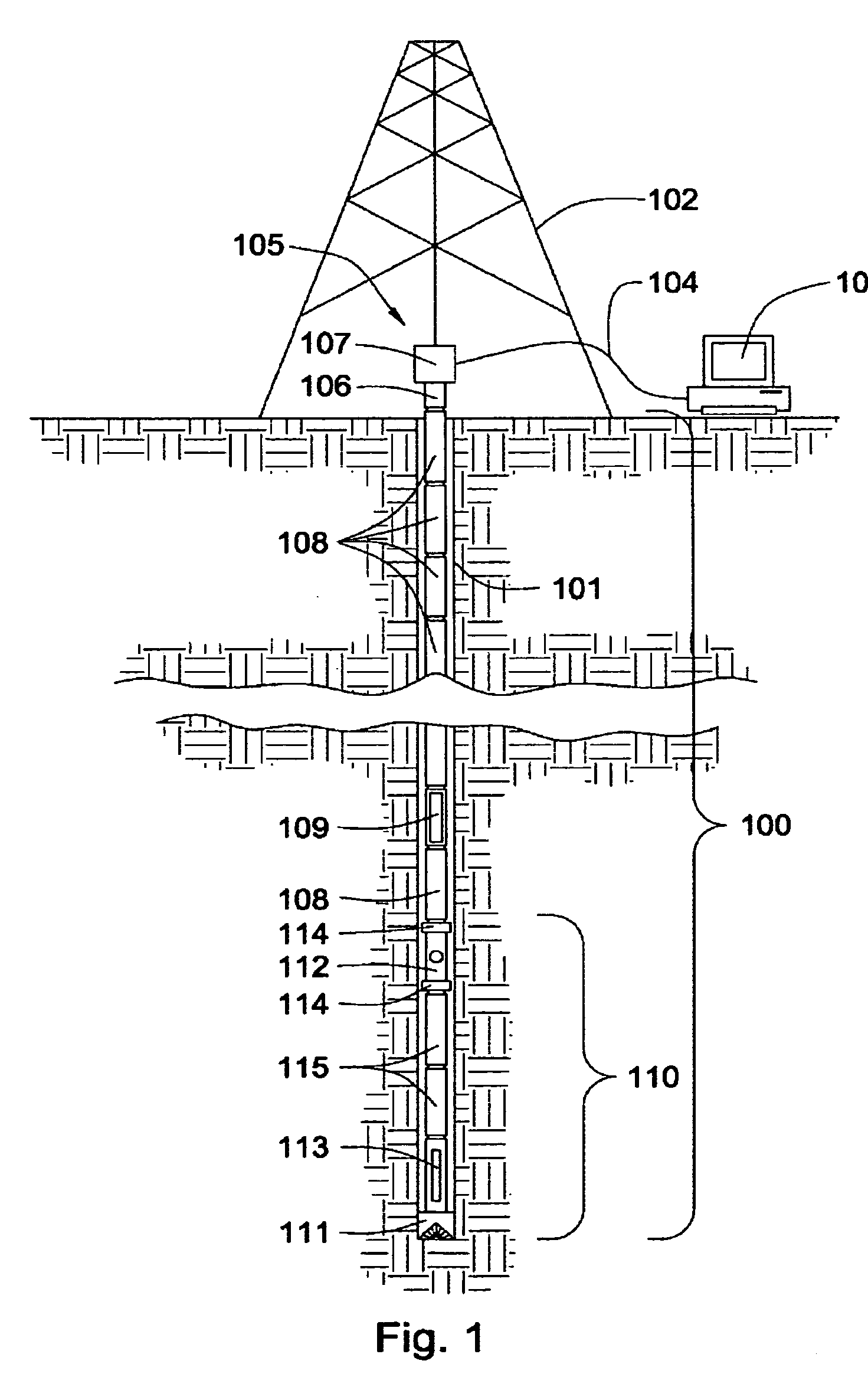
[0041]FIG. 1 shows a cross section of the preferred embodiment of the invention for RVSP MWD. A drill string 100, comprising an integrated data transmission network, is suspended in a well bore 101 from a derrick 102. Surface equipment 103, such as a computer, connects via a cable 104 to a data saver 105. The data saver is adapted to transmit data to and from the downhole portion of the integrated transmission network while the drill string is rotating and progressing forward into the earth. It may comprise an element 106 that rotates with the drill string and an element 107 that does not rotate and connects to the cable 104. The data saver may comprise means for transferring information through a rotating joint, such as a slip ring or an inductive coupler. To avoid need for the cable 104, the data saver may communicate with the surface equipment by wireless means, such as by infrared waves, microwaves, or radio waves, in which case the entire data saver may rotate with the drill st...

example 3

[0054] Referring to FIG. 3, the downhole source 320 is a mud hammer that is controlled from the surface over the telemetry drill string 300. Source 320 also sends a pilot signal to surface equipment 303 over the downhole and surface networks. Downhole seismic receiver 312 is activated from the surface and sends its received waveforms to the surface over the telemetry drill string 300. If receiver 312 contains active means for positioning the seismic sensor against the borehole wall, this means is also activated and controlled from the surface. If the tube wave suppression devices 314 require activation, this, too, is commanded over the drill string from the surface. In this embodiment the drill string 300 is not rotating, but mud is circulated to drive the hammer. All other elements shown remain physically in place, with all downhole elements serving as part of the telemetry drill string, but the seismic functions of these other elements are not active. Thus, by selective command an...

example 4

[0055] The mechanical configuration of FIG. 3 is retained, but the surface computer 303 activates a different set of surface and borehole tools. The drill string 300 continues to drill actively forward during the experiment, with bit 311 serving as the seismic source. The pilot sensors in the bit 311 may be used to provide the bit pilot signal to surface equipment 303 over the telemetry drill string 300. Mud hammer 320 may be also be activated from the surface to augment the seismic and drilling activity of the bit, and pilot sensors in the hammer may be used to augment the pilot signal from the bit 311. (Hammer augmentation may be particularly desired while drilling in soft formations with a shear bit.) The surface receiver 330 is simultaneously activated on command from computer 303. Surface source 350 and mid-string source 340 are not active. If in-string receivers 312, 322 and 332 are not active, the drill-bit seismic experiment of Example 2, FIG. 2 is duplicated. If a mud motor...


PUM


Abstract

An apparatus and method for seismic measurement-while-drilling comprises at least one of a downhole seismic receiver or a downhole seismic source deployed in a telemetry drill string. Preferably both a downhole receiver and a downhole source are deployed in the drill string, the source and receiver being fixed at a pre-determined distance from each other. As drilling progresses into a subterranean formation, a first seismic shot is performed at a first level, producing a model characteristic of the subterranean formation, and at least one subsequent seismic shot is performed at at least one subsequent level, producing at least a second model characteristic of the subterranean formation. The first and at least the second model are used in combination to evaluate the subterranean formation and to evaluate the progress of the drill string relative to the formation.

Description

CROSS-REFERENCE TO RELATED APPLICATIONS None FEDERAL SPONSORSHIP None BACKGROUND OF THE INVENTION [0001] This invention relates to an apparatus and method for seismic measurement-while-drilling (seismic MWD), preferably comprising a downhole transmission network integrated into a drill string. [0002] An outstanding problem in the exploration for new hydrocarbons and in the development of known hydrocarbon reservoirs is determining the location of reflectors in subterranean formations. A reflector is any feature in the formation where there is a change in acoustic impedance. Examples of reflectors include boundaries between different sedimentary formations; faults, cracks, or cavities; zones permeated with different fluids or gases; and zones exhibiting a gradient in pore pressure. [0003] In a surface seismic survey both sources and receivers are positioned at or near the surface. This is the most widely-used type of geophysical survey, but it is hampered by noise, interference, an...

Claims


Application Information

Patent Timeline
Patent Type & Authority Applications(United States)
IPC IPC(8): G01V1/00
CPCG01V1/40
Inventor COX, DALEHALL, DAVID R.HALL, H. TRACYFOX, JOE R.
Owner NOVADRILL
Why Eureka
Try Eureka