Disk array system

a disk array and disk technology, applied in the direction of electrical apparatus construction details, instruments, casings/cabinets/drawers, etc., can solve the problems of low long-term reliability of the disk array system, operational malfunction, and disk drive malfunction, and achieve the effect of effectively cooling densely packed disk drives

Inactive Publication Date: 2006-04-13
HITACHI LTD
View PDF13 Cites 52 Cited by
  • Summary
  • Abstract
  • Description
  • Claims
  • Application Information

AI Technical Summary

Benefits of technology

[0012] It is an object of the present invention to provide a disk array system in which densely-packed disk drives are cooled effectively.

Problems solved by technology

When densely-integrated disk drives are aligned and accommodated in a unit box, heat from the disk drives raises the temperature of the unit box, resulting in malfunction in devices constituting the disk drives.
If cooling is not well performed, the temperatures of the disk drives increase or differ from disk drive to disk drive, resulting in operational malfunction or low long-term reliability of the disk array system.
However, when the aforementioned heat dissipation mechanism such as fins is disposed in the disk unit,-one disk drive takes up a lot of space in the unit box, resulting in decreased density of the disk drives in the unit box.
Because of this, the fin cannot be made large, whereby cooling performance is degraded.
Due to this variation in temperature increase, the temperatures of some disk drives may exceed the tolerance temperature.
To prevent this problem, the gaps between the disk drives need to be made larger, which conflicts with the high-density packaging requirement.

Method used


Image

  • Disk array system
  • Disk array system
  • Disk array system

Examples


first embodiment

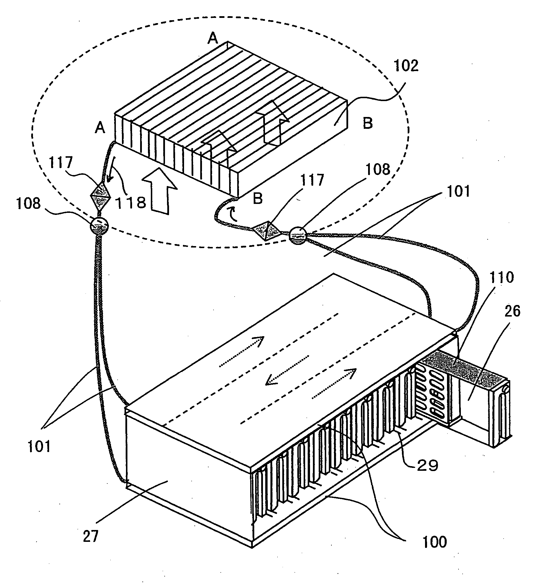
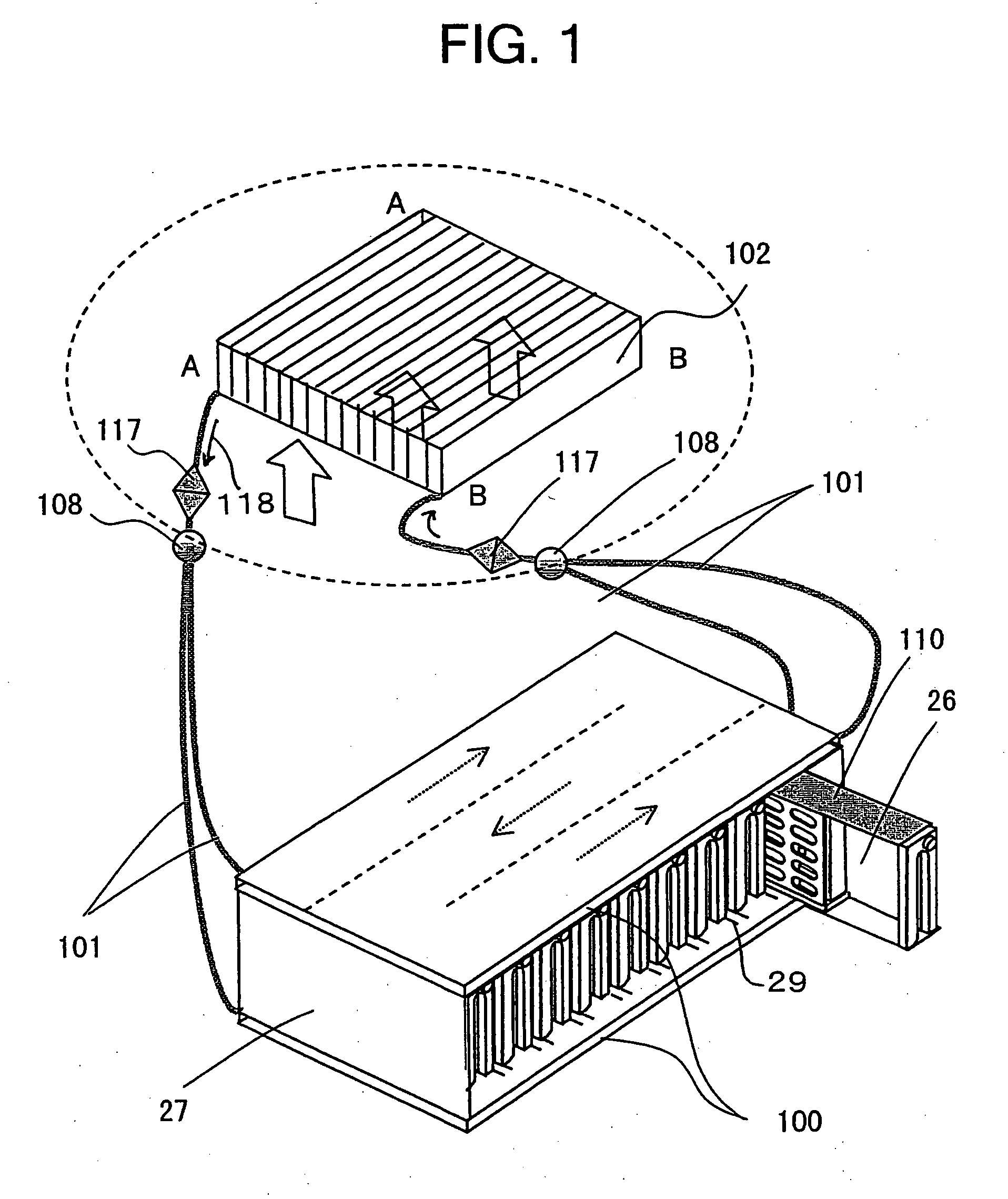
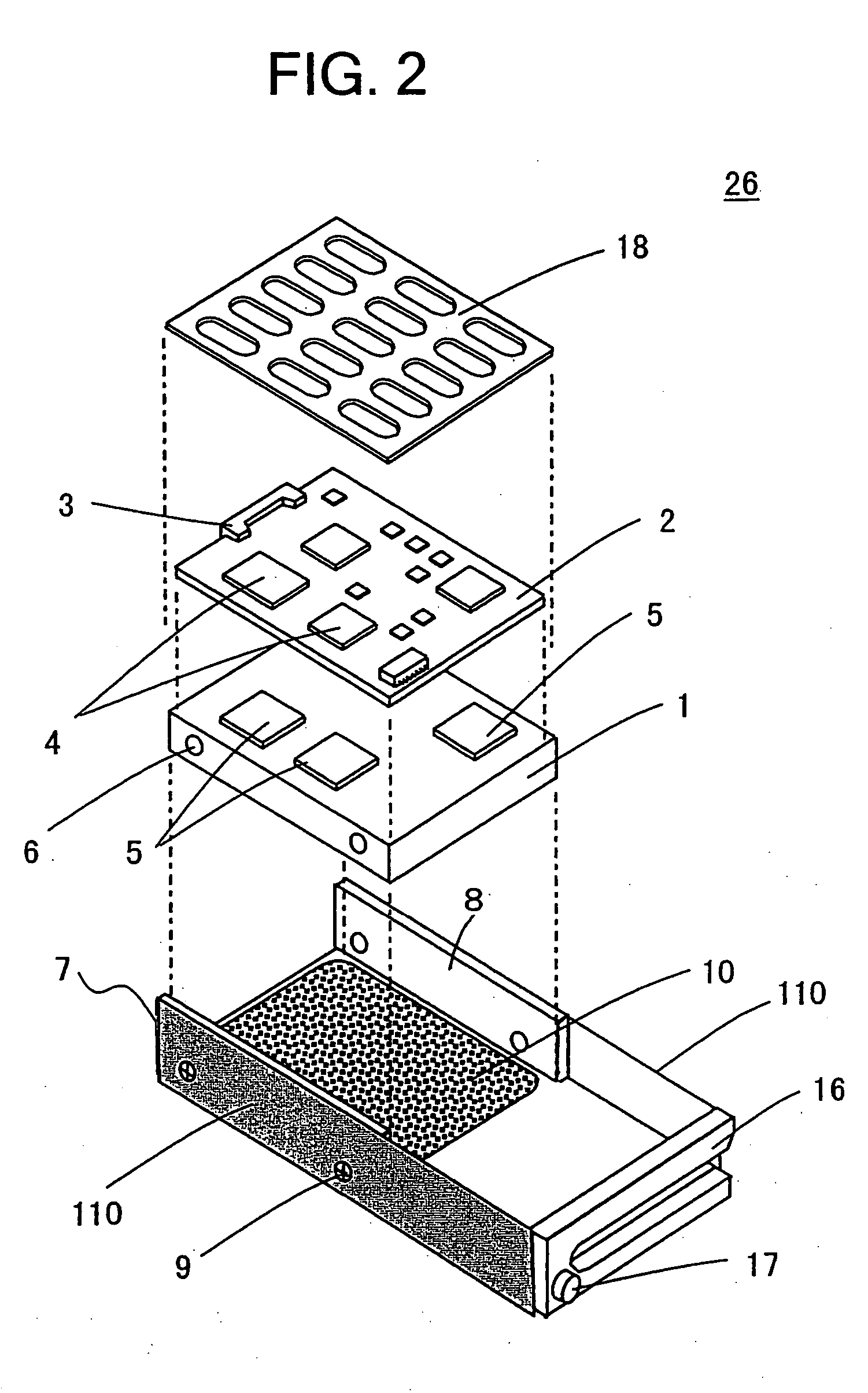
[0038] A first embodiment of the present invention will now be described by referring to FIGS. 1 and 2. FIG. 1 is a perspective view of a disk array system according to the first embodiment. FIG. 2 is an exploded view of a disk drive according to the first embodiment. Referring to FIG. 2, a disk drive 26 includes a disk body 1, a control board 2, a cover 18 for covering the control board 2, and a housing 7. The disk body 1, the control board 2, and the cover 18 are assembled in this order and accommodated in the box-shaped housing 7. Although not illustrated in the drawing, the disk body 1 contains, in a thin case composed of a thermally-conductive material, a magnetic disk, a motor for rotating the magnetic disk, a read / write head for recording information onto the magnetic disk and for reproducing information recorded on the magnetic disk, and an actuator for driving the read / write head, for example.

[0039] The control board 2 disposed on the disk body 1 includes controlling circu...

second embodiment

[0053]FIG. 3 is a perspective view of a housing 7 in a disk array system according to a second embodiment of the present invention. The disk array system of the second embodiment is different from that of the first embodiment shown in FIG. 2 in that projecting strips 112 having triangular cross-sections are disposed on the side surfaces of the housing 7 so as to extend in the longitudinal direction of the housing 7, in place of the heat-transfer-accelerating units 110 of the first embodiment. In the unit box 27, grooves (not shown) are disposed so as to correspond to the projecting strips 112. Accordingly, the housings 7 and the unit box 27 are connected over a sufficiently large contacting area, thereby accelerating the thermal transfer. Moreover, when thermally-conductive grease is applied to the surfaces of the projecting strips 112, thermal transfer is even further accelerated. The projecting strips 112 may also function as guide rails when the housings 7 are inserted into the u...

third embodiment

[0054]FIG. 4 is a perspective view of a housing 7 in a disk array system according to a third embodiment. In FIG. 4, the housing 7 is upside down with the bottom surface facing up. The disk array system of the third embodiment is different from that of the first embodiment shown in FIG. 2 in that guide rails 20 including protruding strips are disposed on one side surface of the housing 7 and a heat-transfer-accelerating unit 110 composed of thermally-conductive rubber is disposed on the surfaces of the protruding strips. The guide rails 20 facilitate positioning of the disk drive 26 when the disk drive 26 is inserted into or removed from the unit box 27.

[0055] According to the disk array system of the third embodiment, a plurality of spring clamps 113 is disposed on the other side surface of the housing 7 that opposes the side surface having the guide rails 20, and heat-transfer-accelerating units 110 to which thermally-conductive rubber is attached are disposed on the surfaces of ...


PUM

PropertyMeasurementUnit
temperatureaaaaaaaaaa
thicknessaaaaaaaaaa
thermally-conductiveaaaaaaaaaa

Abstract

A disk array system includes a plurality of disk drives and at least one unit box including the plurality of disk drives aligned in the thickness direction of the disk drive, each disk drive including a thin case accommodating a recording disk, a read/write head, and a driving mechanism for driving the recording disk and the read/write head, and a control board for controlling the driving mechanism, the control board being mounted on the thin case. In the disk array system, the thin case and the unit box are composed of a thermally-conductive material, the unit box includes surfaces parallel to the thickness direction of the plurality of disk drives, and at least one of the surfaces has a cold plate filled with a refrigerant. Heat generated at the disk drives is transferred to the cold plate, thereby improving cooling performance.

Description

BACKGROUND OF THE INVENTION [0001] 1. Field of the Invention [0002] The present invention relates to a disk array system including a plurality of disk drives that drive disk recording media, and more particularly, to a technique for cooling the disk drives. [0003] 2. Description of the Related Art [0004] With advances in computer technology, high-density modularization and integration of electronic devices for computing systems are being carried out. For example, a compact disk array system including a plurality of disk drives that is highly modularized has been proposed as a recording medium for recording information necessary for a computer system. The highly-modularized disk drives each have a low-profile construction, including a magnetic or optical disk recording medium (recording disk), a disk unit including a read / write head for recording / reproducing information on / from the recording disk in a thin case, a controlling circuit for controlling the disk and the head in the disk ...

Claims


Application Information

Patent Timeline
Patent Type & Authority Applications(United States)
IPC IPC(8): G11B7/085
CPCG11B33/128G11B33/1413G11B33/1426H05K7/20818
Inventor MATSUSHIMA, HITOSHIATARASHI, TAKAYUKIFUKUDA, HIROSHIYAMANA, SHUNSUKE
Owner HITACHI LTD
Why Eureka
Try Eureka