
Curable subgasket for a membrane electrode assembly

a membrane electrode and subgasket technology, applied in the field of fuel cells, can solve the problems of gas leakage, time-consuming, and inability to adapt to mass production, and achieve the effects of reducing the cost of fuel cells

Inactive Publication Date: 2006-04-13
3M INNOVATIVE PROPERTIES CO
View PDF21 Cites 47 Cited by
  • Summary
  • Abstract
  • Description
  • Claims
  • Application Information

AI Technical Summary

Benefits of technology

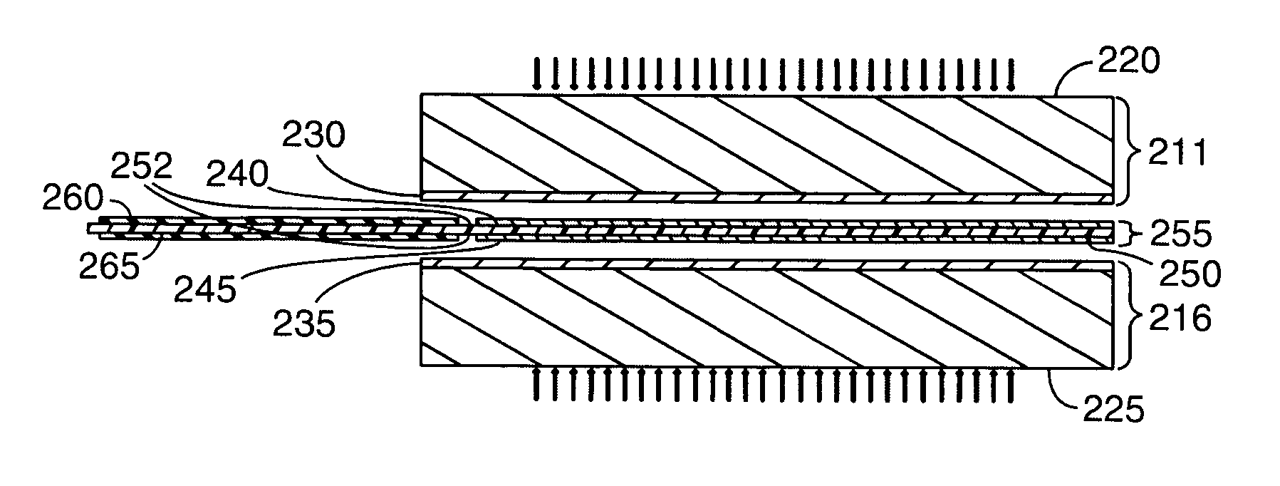
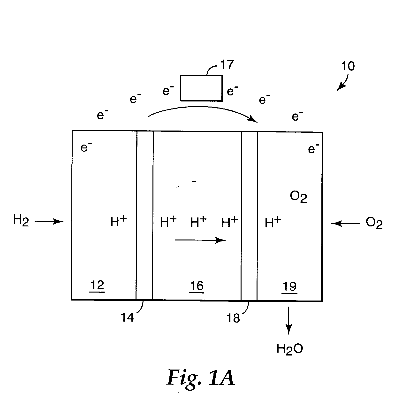
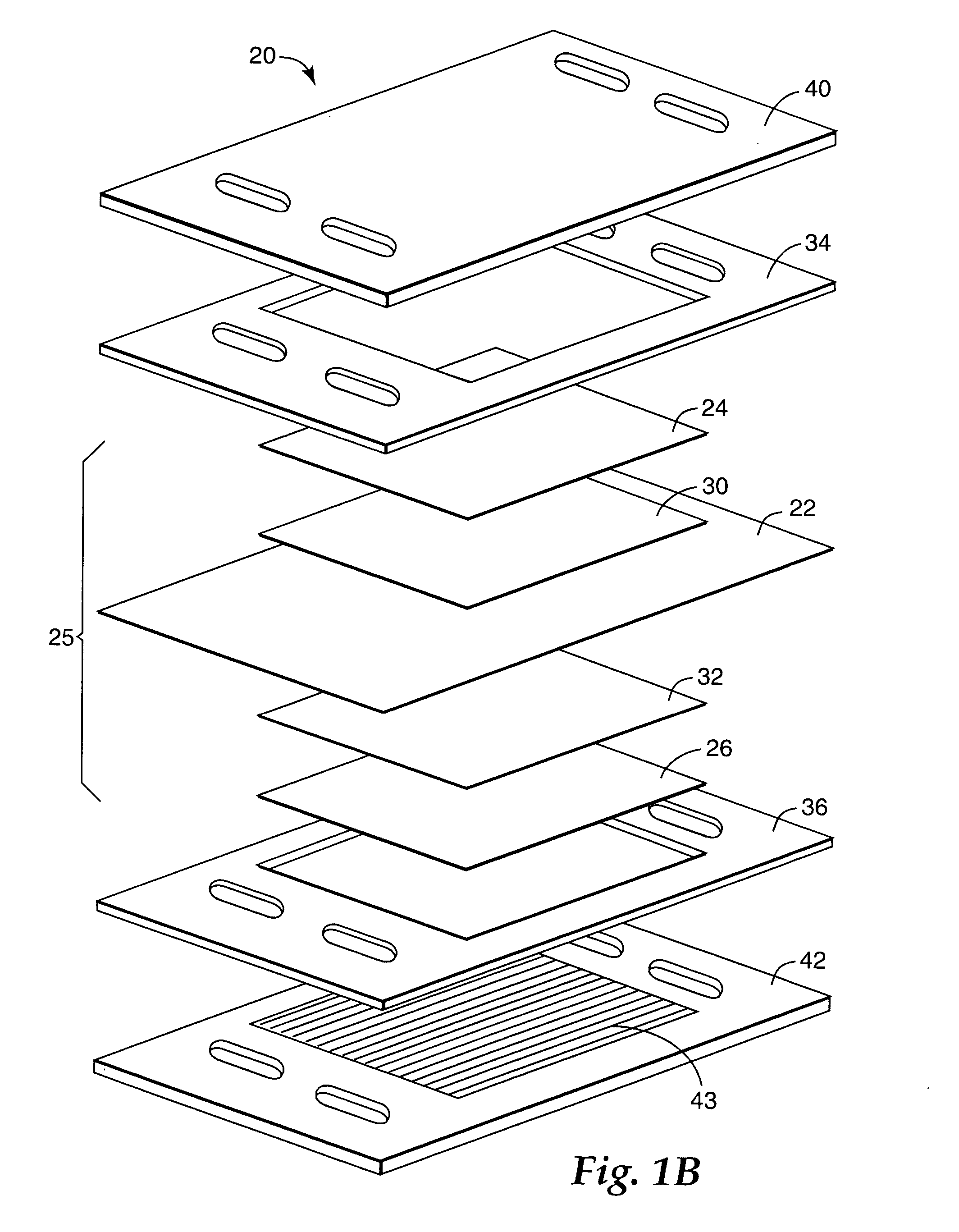
[0006] The present invention is directed to a curable subgasket for a membrane electrode assembly. An embodiment of the invention is directed to a structure for a membrane electrode assembly (MEA). The MEA structure includes a membrane electrode subassembly including a polymer electrolyte membrane, a gas diffusion layer and a catalyst layer between the polymer electrolyte membrane and the gas diffusion layer. The membrane electrode subassembly includes a subgasket, disposed over one or more components of the membrane electrode subassembly. The subgasket is made of a layer of material that is depositable and curable in situ. A peripheral edge of the gas diffusion layer overlaps the subgasket.

Problems solved by technology

Presently, the process of building a stack of fuel cells using conventional approaches is tedious, time-consuming, and not readily adaptable for mass production.
Misalignment of even a few components can lead to gas leakage, hydrogen crossover, and performance / durability deterioration.
Although an MEA can fail in a number of ways, MEAs are typically taken out of service with gas crossover exceeds a certain rate, indicating the membrane has been punctured mechanically or eroded in thickness due to chemical decay.

Method used


Image

  • Curable subgasket for a membrane electrode assembly
  • Curable subgasket for a membrane electrode assembly
  • Curable subgasket for a membrane electrode assembly

Examples


example 1

[0146] A UV curable dispersion mixture was prepared comprising 10 parts poly butadiene dimethacrylate oligomer (available under the trade designation “CN301” from Sartomer, Exton, Pa.) and 3 parts 1,6-hexanediol diacrylate (available under the trade designation “SR238” from Sartomer, Exton, Pa. 19341). Around 5% by weight of an α-hydroxy-acetophenone type photoinitiator (available under the trade designation SR1129 from Sartomer, Exton, Pa.) was used. This dispersion had a viscosity of around 1000 cps. Cast Nafion® 1100 membrane 1.1 mil in thickness was peeled off the carrier liner in the first step. To facilitate handling of the thin membrane, sections were taped onto a polyethyleneterepthalate (PET) carrier web that was threaded up on a screen printer. Dispersion was applied to said membrane using a patterned Gallus type screen. Screen mesh with 240 openings per inch was used to deposit a protective film of ˜1 mil thick on each side of the membrane. After each coating layer was ap...

example 2

[0147] The dispersion mixture described in Example 1 above was printed onto membrane while the membrane was still attached to its PET carrier liner. Cast Nafion® 1100 membrane 1.1 mils thick on PET liner 3 mils thick, was threaded up from unwind to windup on a TELSTAR (Burnsville, Minn.) screen printing machine. The UV curable dispersion mixture was deposited on the PEM to a thickness of approximately 1 mil. The dispersion was cured with a D type bulb as in example 1. The membrane was then peeled off the liner. The resulting membrane had a frame of protective material on one side, applied around a window opening that was uncoated

example 3

[0148] Samples of a UV protective varnish (Trimethylolpropane Triacrylate Ester) were obtained from Northern Coatings (Menominee, Mich.). Using the method of Example 2, the UV varnish was applied to a thickness of 2 mils onto the membrane. The dispersion was cured with a D type bulb as in example 1. The membrane was then peeled off the liner. The resulting membrane had a frame of protective material applied around a window opening that was uncoated. Although the protected membrane was significantly more resistant to stretching and deformation when tested by hand, the coating delaminated when the membrane was exposed to boiling water.


PUM

PropertyMeasurementUnit
thicknessaaaaaaaaaa
thicknessaaaaaaaaaa
thicknessaaaaaaaaaa

Abstract

A subgasket for a membrane electrode assembly is deposited on a surface of a MEA component and cured in situ. A membrane electrode subassembly includes a polymer electrolyte membrane, a gas diffusion layer and a catalyst layer between the polymer electrolyte membrane and the gas diffusion layer. The membrane electrode subassembly includes a subgasket, disposed over one or more components of the membrane electrode subassembly. The subgasket is made of a layer of material that is depositable and curable in situ. A peripheral edge of the gas diffusion layer overlaps the subgasket.

Description

FIELD OF THE INVENTION [0001] The present invention relates generally to fuel cells and, more particularly, to a curable subgasket for a membrane electrode assembly. BACKGROUND OF THE INVENTION [0002] A typical fuel cell power system includes a power section in which one or more stacks of fuel cells are provided. The efficacy of the fuel cell power system depends in large part on the integrity of the various contacting and sealing interfaces within individual fuel cells and between adjacent fuel cells of the stack. [0003] Presently, the process of building a stack of fuel cells using conventional approaches is tedious, time-consuming, and not readily adaptable for mass production. By way of example, a typical 5 kW fuel cell stack can include some 80 membrane electrode assemblies (MEAs), some 160 flow field plates, and some 160 sealing gaskets. These and other components of the stack must be carefully aligned and assembled. Misalignment of even a few components can lead to gas leakag...

Claims


Application Information

Patent Timeline
Patent Type & Authority Applications(United States)
IPC IPC(8): H01M2/08H01M8/10H01M4/94B05D5/12
CPCH01M8/0273H01M8/028H01M8/0286H01M8/0297H01M8/1004Y02E60/50H01M8/02H01M4/86H01M4/88H01M8/242
Inventor STEGINK, DAVID W.MEKALA, DAVID R.
Owner 3M INNOVATIVE PROPERTIES CO
Learn More