Ultrasonic imaging apparatus

a technology of ultrasonic imaging and imaging apparatus, which is applied in the direction of ultrasonic/sonic/infrasonic diagnostics, instruments, and using reradiation. it can solve the problems of difficult to identify the tissue property of a tumor or the like, difficult to distinctively image the tissue property of an entire range that includes both the boundaries and the internal region, and achieve the effect of improving the quality and efficiency of medical diagnoses using ultrasonic images

Inactive Publication Date: 2006-04-13
FUJIFILM CORP +1
View PDF15 Cites 35 Cited by
  • Summary
  • Abstract
  • Description
  • Claims
  • Application Information

AI Technical Summary

Benefits of technology

[0019] According to the present invention, in boundaries between different tissues and a first region and/or a second region divided by the boundaries, images generated by processing using appropriate algorithms according to the respective regions are arranged, and the...

Problems solved by technology

Accordingly, it is extremely difficult to determine tissue property of a tumor or the like, or visually recognize soft tissues separately from hard tissues in a region like the vicinity of a bone part where soft tissues such as muscles and hard tissues such as bones, tendons, and nucleus pulposus are intricate.
On the other hand, position information on boundaries can be obtained by phase matching plural reception signals, but appropriate image display can not be performed with respect to a region having an indistinctive outline like a uniform interna...

Method used


Image

  • Ultrasonic imaging apparatus
  • Ultrasonic imaging apparatus
  • Ultrasonic imaging apparatus

Examples


first embodiment

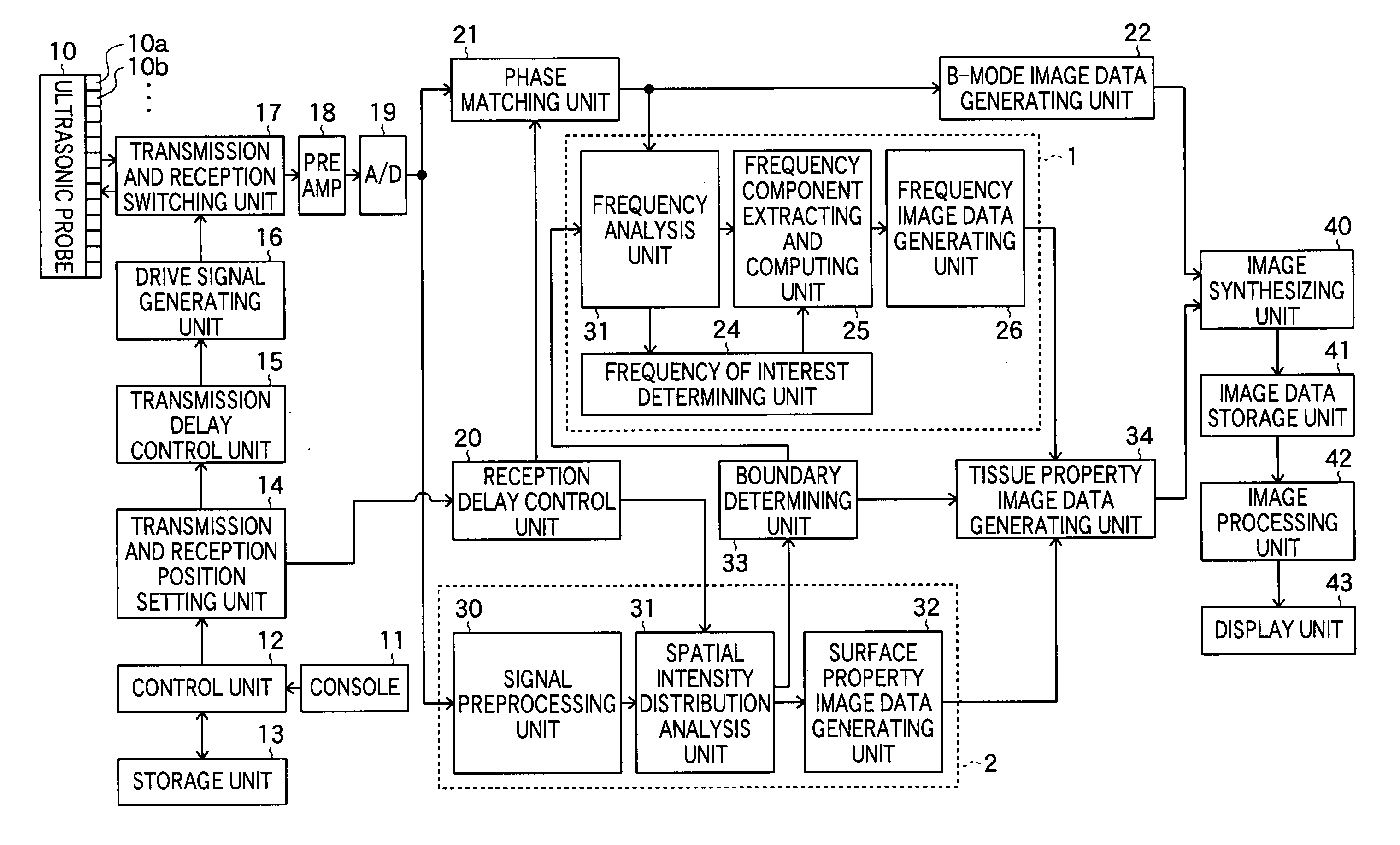
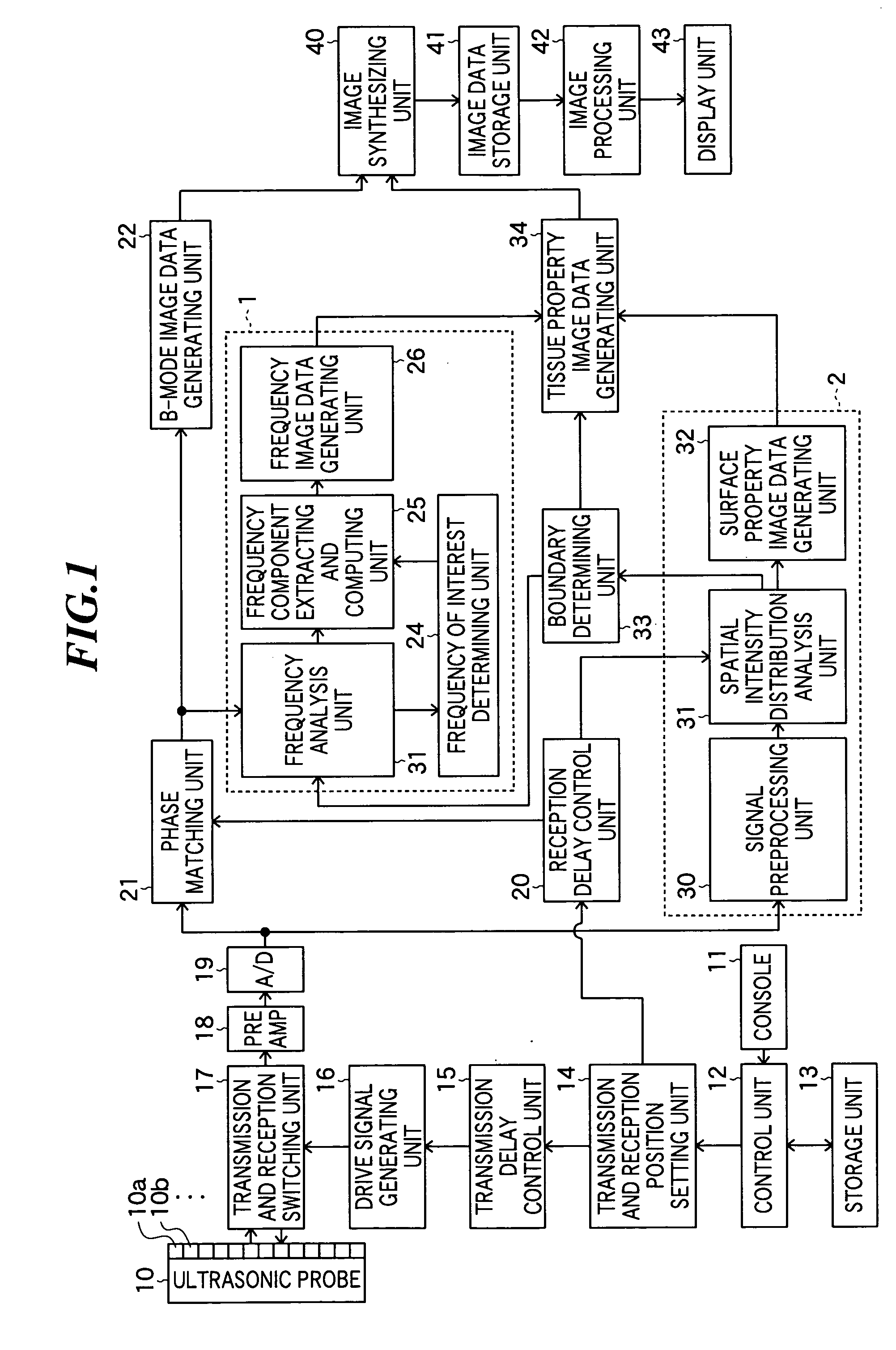
[0041]FIG. 1 is a block diagram showing a constitution of an ultrasonic imaging apparatus according to the present invention. The ultrasonic imaging apparatus according to the embodiment includes an ultrasonic probe 10, a console 11, a control unit 12, a storage unit 13, a transmission and reception position setting unit 14, a transmission delay control unit 15, a drive signal generating unit 16, a transmission and reception switching unit 17, a preamplifier (PREAMP) 18, and an A / D converter 19.

[0042] The ultrasonic probe 10 is used by being abutted on the object to transmit ultrasonic waves to an object to be inspected and receive ultrasonic waves reflected from the object. The ultrasonic probe 10 includes plural ultrasonic transducers 10a, 10b, . . . for transmitting ultrasonic beams based on applied drive signals and receiving propagating ultrasonic echoes to output reception signals. These ultrasonic transducers 10a, 10b, . . . are arranged in a one-dimensional or two-dimensiona...

second embodiment

[0102] Next, an ultrasonic imaging apparatus according to the present invention will be described. FIG. 8 is a block diagram showing a constitution of the ultrasonic imaging apparatus according to the embodiment.

[0103] As shown in FIG. 8, this ultrasonic imaging apparatus has a boundary extracting unit 35 in place of the boundary determining unit 33 shown in FIG. 1. Other constitution is the same as that of the ultrasonic imaging apparatus shown in FIG. 1.

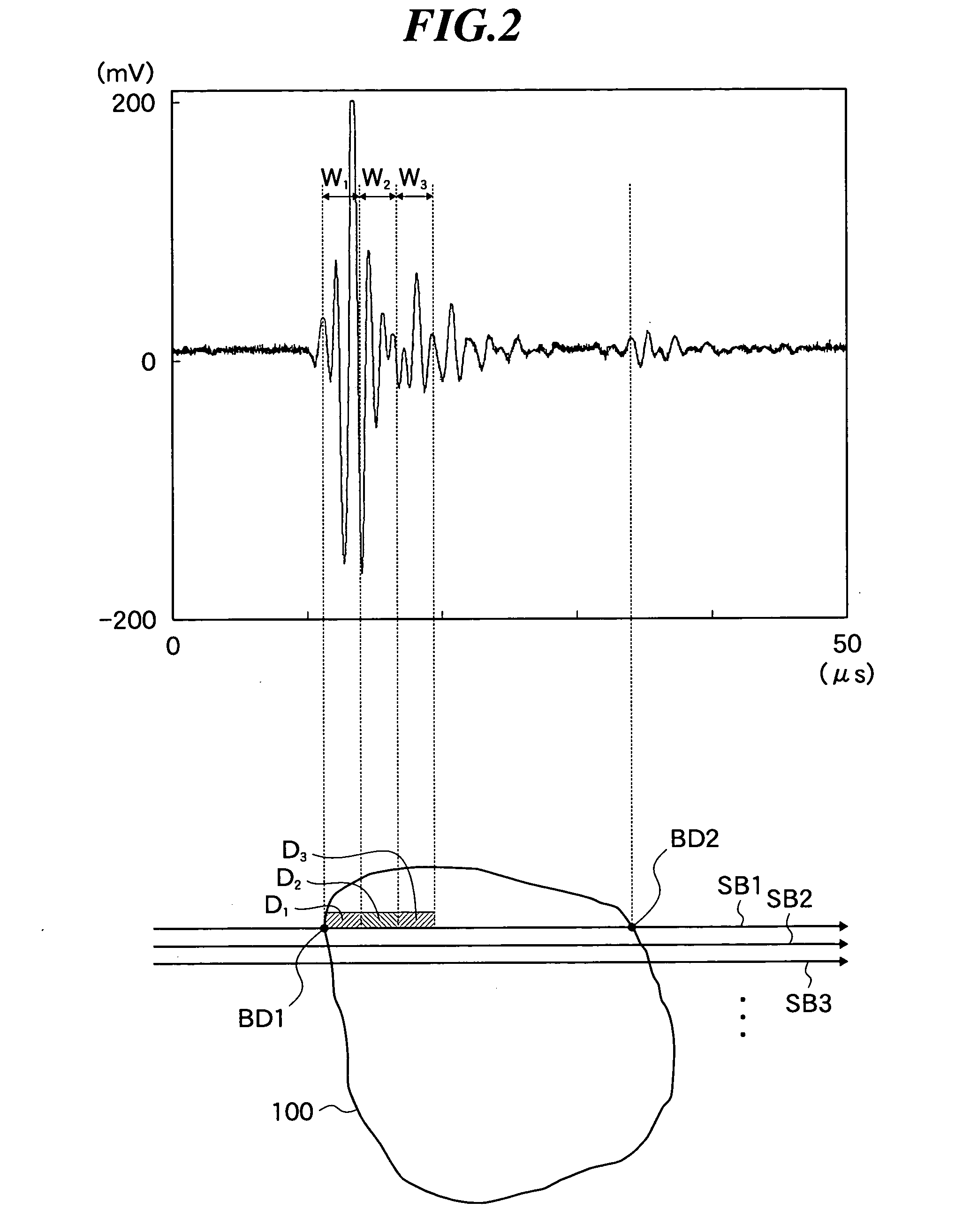
[0104] The boundary extracting unit 35 generates boundary position information by extracting boundaries within the object based on the sound ray data generated in the phase matching unit 21. Here, referring to FIG. 2 again, at the boundary of the reflector, voltages of the signals representing sound rays drastically change. Accordingly, the boundary extracting unit 35 can extract positions where the voltages of the signals representing sound rays are peaked as boundaries (e.g., boundary BD2). Alternatively, in the case where, in a...

third embodiment

[0107] Next, an ultrasonic imaging apparatus according to the present invention will be described by referring to FIGS. 9 and 10. FIG. 9 is a block diagram showing a constitution of the ultrasonic imaging apparatus according to the embodiment. As shown in FIG. 9, this ultrasonic imaging apparatus further has a boundary correction unit 50 in addition to the ultrasonic imaging apparatus shown in FIG. 1. Other constitution is the same as that of the ultrasonic imaging apparatus shown in FIG. 1.

[0108]FIG. 10 is a diagram for explanation of an operation of the boundary correction unit 50. In FIG. 10, gray regions show pixels 121 that have been determined to be boundaries by the boundary determining unit 33 of plural pixels 120 forming an ultrasonic image.

[0109] Here, as described above, the boundary determining unit 33 determines whether the respective regions on sound rays are boundaries or not. Accordingly, depending on scanning density or solving power of ultrasonic beams, like regio...


PUM


Abstract

An ultrasonic imaging apparatus capable of generating ultrasonic images including boundaries between different tissues and regions divided by the boundaries in which property of boundaries and the respective tissues can be distinctly identified. The ultrasonic imaging apparatus includes ultrasonic transducers for transmitting and receiving ultrasonic waves to output reception signals; a boundary information generating unit for generating information representing positions of boundaries based on the reception signals; a first image data generating unit for generating first image data representing property of a first region and/or a second region divided by the boundaries; a second image data generating unit for generating second image data representing property of boundaries based on the reception signals; and a tissue property image data generating unit for generating tissue property image data by locating images represented by the first and second image data in the region, based on the boundary position information.

Description

BACKGROUND OF THE INVENTION [0001] 1. Field of the Invention [0002] The present invention relates to an ultrasonic imaging apparatus for transmitting and receiving ultrasonic waves to perform imaging of organs, bones, etc. within a living body thereby generating ultrasonic images to be used for diagnosis. [0003] 2. Description of a Related Art [0004] In an ultrasonic imaging apparatus to be used for medical diagnoses, an ultrasonic probe including plural ultrasonic transducers having transmitting and receiving functions of ultrasonic waves is used. When an ultrasonic beam formed by synthesizing plural ultrasonic waves is transmitted from such an ultrasonic probe to an object to be inspected, the ultrasonic beam is reflected at a boundary between regions having different acoustic impedances, i.e., between different tissues from each other within the object. Thus generated ultrasonic echoes are received and an image is constructed based on the intensity of the ultrasonic echoes, and t...

Claims


Application Information

Patent Timeline
IPC IPC(8): A61B8/06
CPCA61B8/08G01S7/52071G01S15/8977
Inventor KARASAWA, HIROYUKI
Owner FUJIFILM CORP
Why Eureka
Try Eureka