Farfield analysis of noise sources

a farfield analysis and noise source technology, applied in the field of farfield analysis of noise sources, can solve the problems of not being able to fully damage the transducer, not being able to use the well-known nearfield acoustic holography (nah) and being near the sour

Active Publication Date: 2006-04-13
WAYNE STATE UNIV
View PDF2 Cites 38 Cited by
  • Summary
  • Abstract
  • Description
  • Claims
  • Application Information

AI Technical Summary

Benefits of technology

[0006] The proposed FANS algorithms are totally different from beamforming technique since it is developed for source diagnostics, but not for target identification. FANS aim at diagnosing the source strength distribution on an arbitrarily shaped object ...

Problems solved by technology

For example, in analyzing the distribution of vehicle pass-by noise source or that of turbulence over a car body inside a wind tunnel, or the strength of a hot jet engine or that of wind turbine, it will be nearly impossible to place an array of microphones next to the source.
This is because the presence of any measurement devices near a source may either completely alter the acoustic pressure field that is being measured such as in diagnosing sources of vehicle pass-by noise, or the condition and environment are so hostile that it can completely damage a transducer such as in the case of a hot jet engine, or the only way to measure the acoustic pressure is to do it in a far field such as in the case of a wind turbine.
Under these conditions, the well-known nearfield acoustic holography (NAH) is not an option, even though it is very accurate and can provide all the encompassing acoustic quantities generated by a sound source.
It is emphasized that in these circumstances, it will not be possible to obtain precise measurements of an acoustic pressure field and only an estimate of the acoustic pressure can be made.
Nevertheless, in practice such adversary ...

Method used


Image

  • Farfield analysis of noise sources
  • Farfield analysis of noise sources
  • Farfield analysis of noise sources

Examples


Embodiment Construction

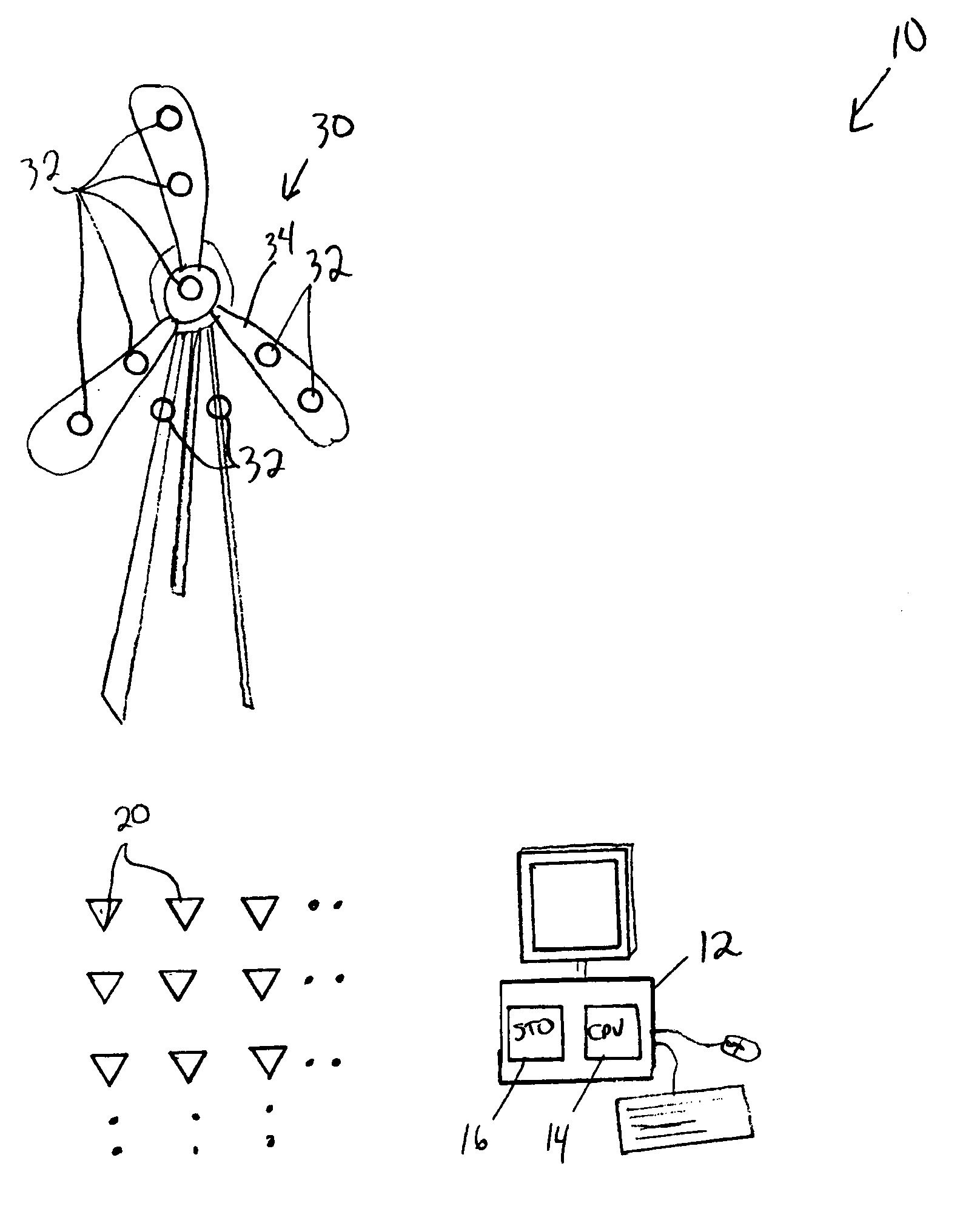
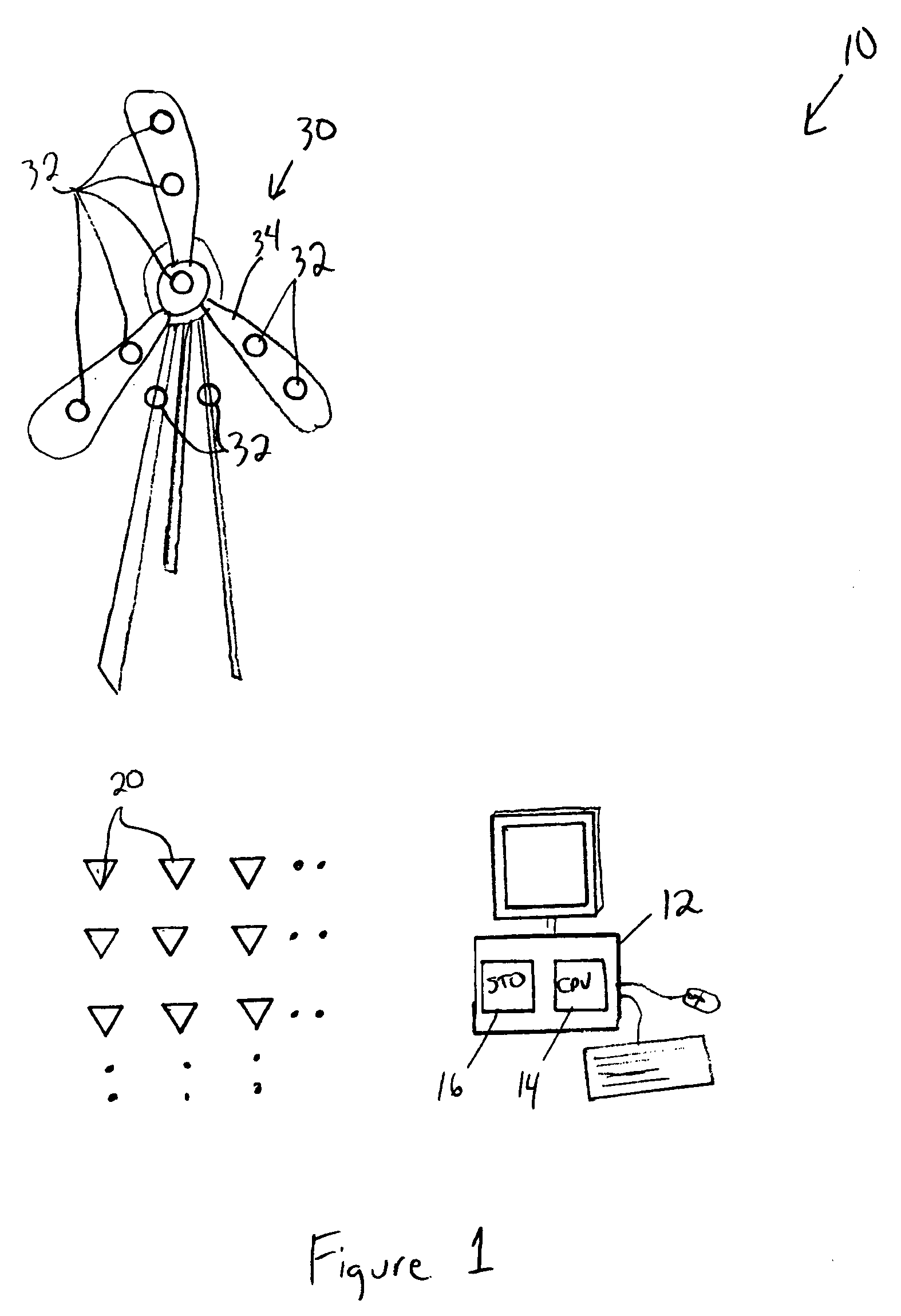
[0010] A noise diagnostic system 10 according to the present invention includes a computer 12 having a processor 14 and storage 16 including memory and mass storage, such as magnetic, electronic and / or optical storage. A plurality of transducers 20, such as microphones, measure sound pressure and send signals to the computer 12 indicating the sound pressure at the location of the transducers 20.

[0011] The noise diagnostic system 10 of the present invention uses a novel algorithm, described below as the “FANS algorithm,” to diagnose noise from a target source 30 whose dimensions, geometry and location are generally known but not necessarily precisely. The algorithm is stored in storage 16 and executed by the processor 14 in the computer 12. In the method according to the invention, a plurality of virtual noise sources 32 are defined on a surface 34 of the target source 30. In the noise diagnostic system 10, the virtual noise sources 32 are spherical wave sources.

[0012] FANS algorit...


PUM


Abstract

An algorithm diagnoses the noise source strength distribution on an arbitrarily shaped object based on acoustic pressures measured in the far field, known as FANS. FANS enable one to acquire a quick estimate of the acoustic pressure at locations that are off limit to traditional measurement microphones. Generally, in the method of the present invention, the noise source is modeled in terms a plurality of virtual spherical wave sources distributed on an auxiliary surface conformal to a source boundary from the inside, but not on the source boundary itself. Sound is then measured at a plurality of measurement points external to the source boundary. The sound field is reconstructed on the source boundary surface itself.

Description

BACKGROUND OF THE INVENTION [0001] The present invention provides a methodology for farfield analysis of noise sources (FANS) that represents a new concept for remote diagnostics of noise sources and for revealing the distribution of strengths of a sound source that is otherwise hard to obtain due either to limitations on the measurement devices or to inaccessibility of measurement transducers. For example, in analyzing the distribution of vehicle pass-by noise source or that of turbulence over a car body inside a wind tunnel, or the strength of a hot jet engine or that of wind turbine, it will be nearly impossible to place an array of microphones next to the source. This is because the presence of any measurement devices near a source may either completely alter the acoustic pressure field that is being measured such as in diagnosing sources of vehicle pass-by noise, or the condition and environment are so hostile that it can completely damage a transducer such as in the case of a ...

Claims


Application Information

Patent Timeline
IPC IPC(8): G06F15/177
CPCG01H3/125G01H17/00
Inventor WU, SEAN F.
Owner WAYNE STATE UNIV
Why Eureka
Try Eureka