

External ribbed furnace tubes
- Summary
- Abstract
- Description
- Claims
- Application Information
AI Technical Summary
Benefits of technology
Problems solved by technology
Method used
Image

Examples
examples
[0049] For the purposes of the modeling Applicants used computational fluid dynamics (CDF) techniques using Fluent® software for a 3 dimensional mesh having 85,000 grid cells to represent the surface of the tube.
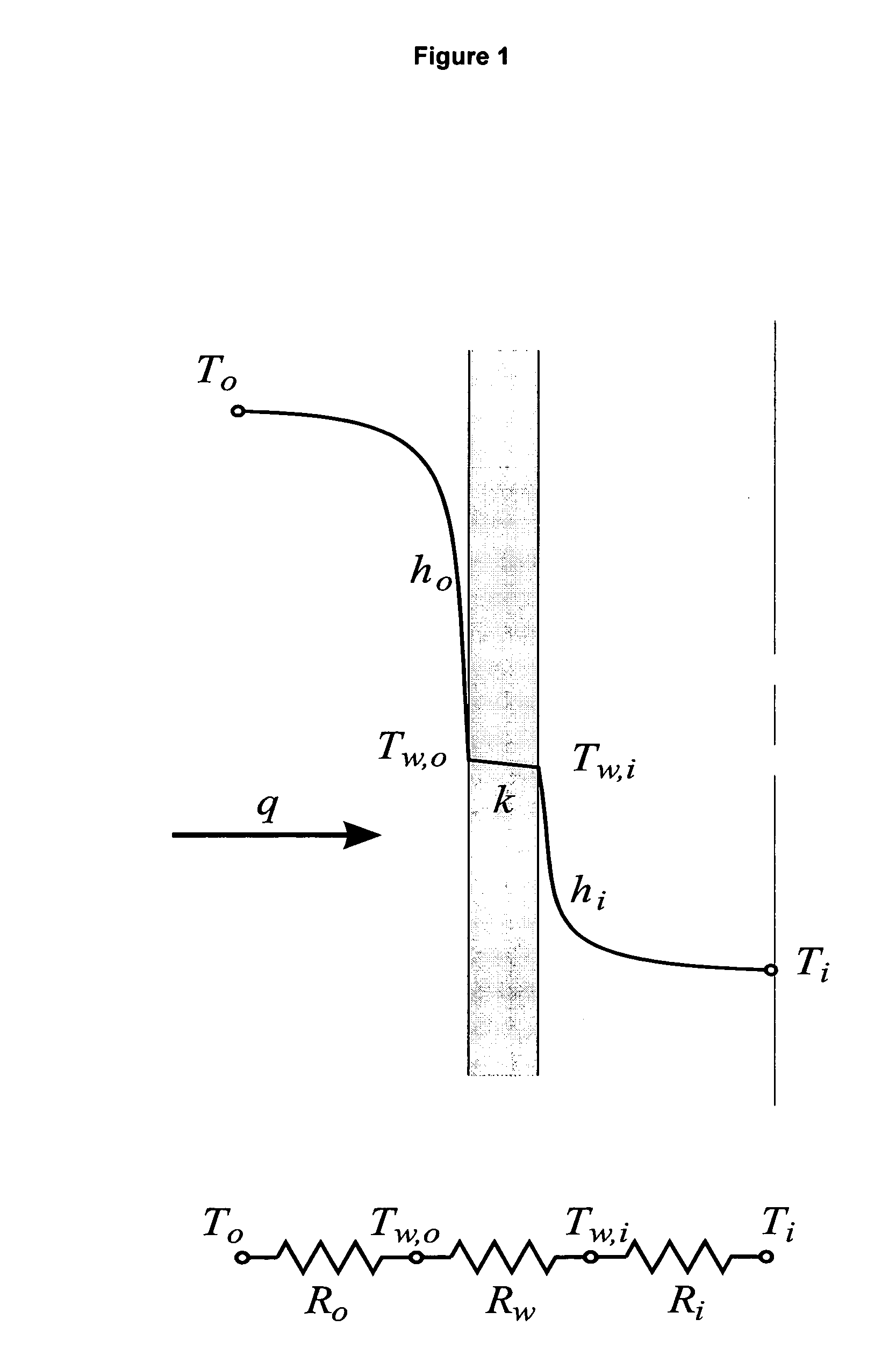
[0050] The steady-state heat transfer for an element of a coil furnace tube is frequently expressed in terms of an overall heat transfer coefficient U, defined by the relation:
q=UAΔT (1)
where A is some suitable area for heat transfer. Using, an electrical resistance analogy (FIG. 1), the above equation can be written as: q=2π l(To-Ti)1[ho+Fsɛgσ To4-Fsɛg / wσ Tw,o4To-Tw,o] ro+ln(ro / ri)k+1hiri(2)
where ho and hi are the external and internal convective heat transfer coefficients, respectively, k is the thermal conductivity of the wall, Fs is a shape factor, εg and εg / w are gas emmissivity and gas absorbtivity parameters, respectively, σ is the Stefan-Boltzmann constant and Tw,o is the wall temperature at the outer surface of the tube. The three terms in the...
experiment 1
[0061] In the first part of this study, the rib height, rib spacing and rib thickness for square ribs was varied. The overall results are shown in Table 3 below. For the first case (1), the ribs are spaced too closely together (P / e) and a recirculation region spanning the gap between the ribs is set up, thus reducing the effectiveness of the ribs. In the second case (2), there is a reattachment point to the convection flow in the furnace between the ribs, thus giving better results. When the rib spacing was increased even further (case 3), the increase in heat flux started to decrease, due to the large distance between ribs. These results indicate that an almost 20% increase in convective / conductive heat transfer is possible with external ribs, and greater increases should be possible with optimization of the rib geometry.
[0062] Next, the relative rib height e / D was reduced by half (cases 4 and 5) which resulted in very marginal increases in heat flux. This was due to the insignifi...
experiment 2
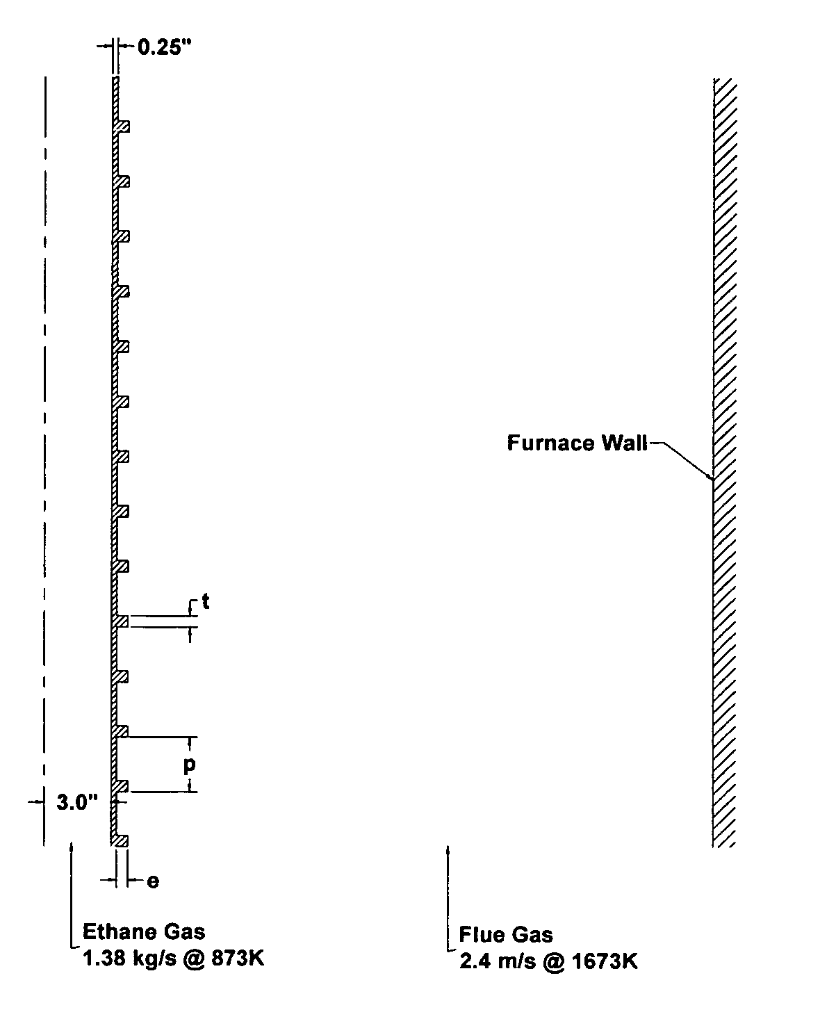
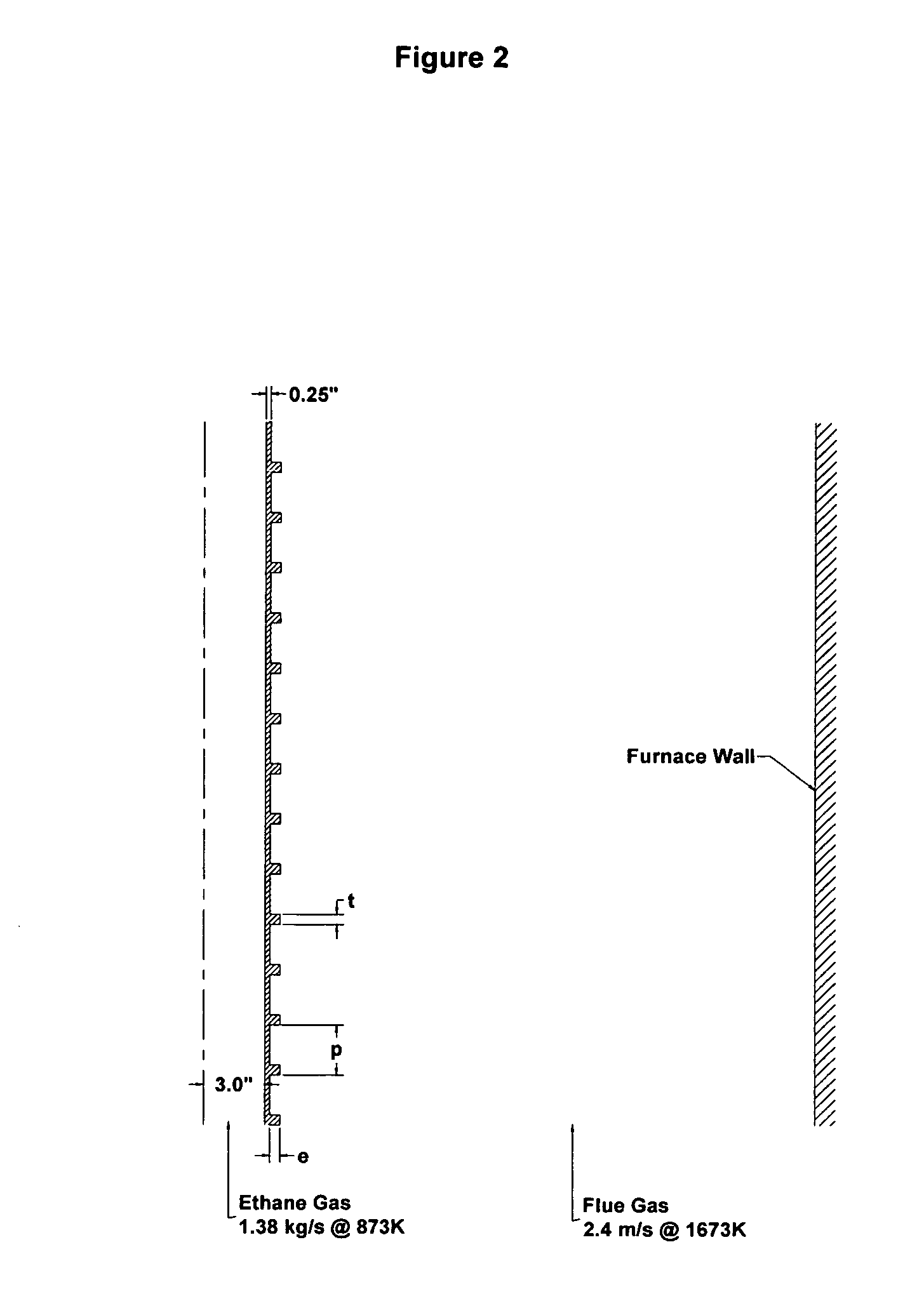
[0064] Next, a comparison of rib geometry with a constant rib height, thickness and spacing was conducted. Square, semi-circular and triangular ribs of the geometry shown in FIG. 2 were simulated and the results are given in Table 4. The semi-circular and triangular shapes were chosen since they may be easier to manufacture with an external coating procedure.
TABLE 4CFD Comparison of Convective Heat Transfer for Square,Semi-Circular and Triangular External Transverse RibsRib% Change inCaseGeometrye / DP / et / eHeat Flux5Square0.077620.646Semi-circular0.077625.47Triangular0.077625.4
[0065] The square ribs are so poor because they don't allow the furnace gas to penetrate between the ribs, contrary to the other two geometric configurations. In addition, the triangular ribs have the smallest temperature gradient from rib root to tip, followed closely by the semi-circular case; the square ribs have the largest root-to-tip temperature gradient.
PUM
| Property | Measurement | Unit |
|---|---|---|
| Fraction | aaaaa | aaaaa |
| Fraction | aaaaa | aaaaa |
| Fraction | aaaaa | aaaaa |
Abstract
Description
Claims
Application Information