Lighting control circuit for vehicle lamps

a technology for controlling circuits and vehicle lamps, applied in the direction of electric variable regulation, process and machine control, instruments, etc., can solve the problems of inability to adequately and consistently supply predetermined current, increase the load on the switching regulator, and inability to always satisfactorily supply a predetermined current to individual led blocks, so as to prevent interference with safe driving and prevent interference. effect of safe driving

Inactive Publication Date: 2006-04-20
KOITO MFG CO LTD
View PDF3 Cites 73 Cited by
  • Summary
  • Abstract
  • Description
  • Claims
  • Application Information

AI Technical Summary

Benefits of technology

[0019] Under the control of the series regulator, a predetermined current is supplied to multiple parallel connected semiconductor light sources. Further, during a process wherein the switching regulator, in accordance with the current states of the series regulators, adjusts to the maximum the voltage to be output to the semiconductor light sources upon the occurrence of an abnormality in a voltage applied to the switching devices or upon the reception of the comparison results obtained by the comparators, e.g., when a specific semiconductor light source, or a circuit associated with the semiconductor light source, is disconnected (opened) and the voltage obtained by the corresponding comparator, as indicated by the comparison results, is increased, or when a specific semiconductor light source is short-circuited or a voltage to be applied to the semiconductor device is raised due to leakage, the state of the switching device whereat the abnormality has occurred is set to the safe state, e.g., the operation of the switching device is halted. Furthermore, when the output voltage of the switching regulator drops abnormally, e.g., when the output side of the switching regulator is short-circuited because of a ground fault on the anode side of a semiconductor light source and the operating state of the switching regulator is controlled in the safe state, the operation of the switching regulator is halted. Therefore, according to this arrangement, a predetermined current can always be supplied to the normal semiconductor light sources, and when an abnormality at a specific semiconductor light source or in a circuit associated with this light source occurs, the remaining normal semiconductor light sources can be protected.
[0020] As apparent from this explanation, a predetermined current can be consistently supplied to normal semiconductor light sources, and when an abnormality occurs in one of the semiconductor light sources, or in an associated circuit, the remaining normal semiconductor light sources can be protected.
[0025] The protection control operation performed by the plurality of protection controllers, which set the operating state of the switching devices to the safe state, is monitored, and an operation halt instruction is issued to the switching regulator when the number of protection controllers that performed the protection operation has reached the predetermined number. With this arrangement, all the semiconductor light sources can be turned off to force a driver to repair an abnormal portion, so that interference with safe driving can be prevented.
[0026] As apparent from this explanation, all the semiconductor light sources can be turned off to force a driver to repair an abnormal portion, so that interference with safe driving can be prevented.

Problems solved by technology

However, when the output of the switching regulator is short-circuited, or is disabled by a ground-fault, an increased load will be imposed on the switching regulator, which will malfunction if the power load becomes excessive.
However, this arrangement cannot always satisfactorily supply a predetermined current to the individual LED blocks.
That is, since the current supplied to each LED block is not monitored, this arrangement cannot adequately and consistently supply a predetermined current to all the LED blocks, even when all the LED blocks are in the normal state.

Method used


Image

  • Lighting control circuit for vehicle lamps
  • Lighting control circuit for vehicle lamps
  • Lighting control circuit for vehicle lamps

Examples


first embodiment

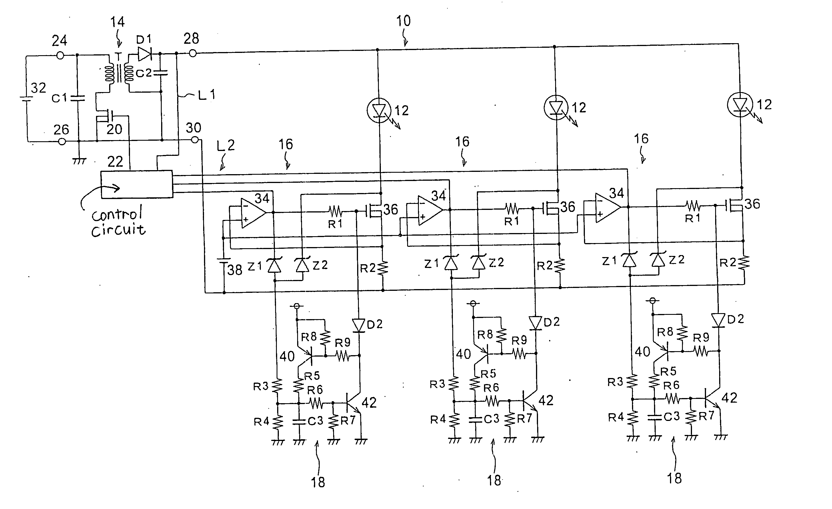
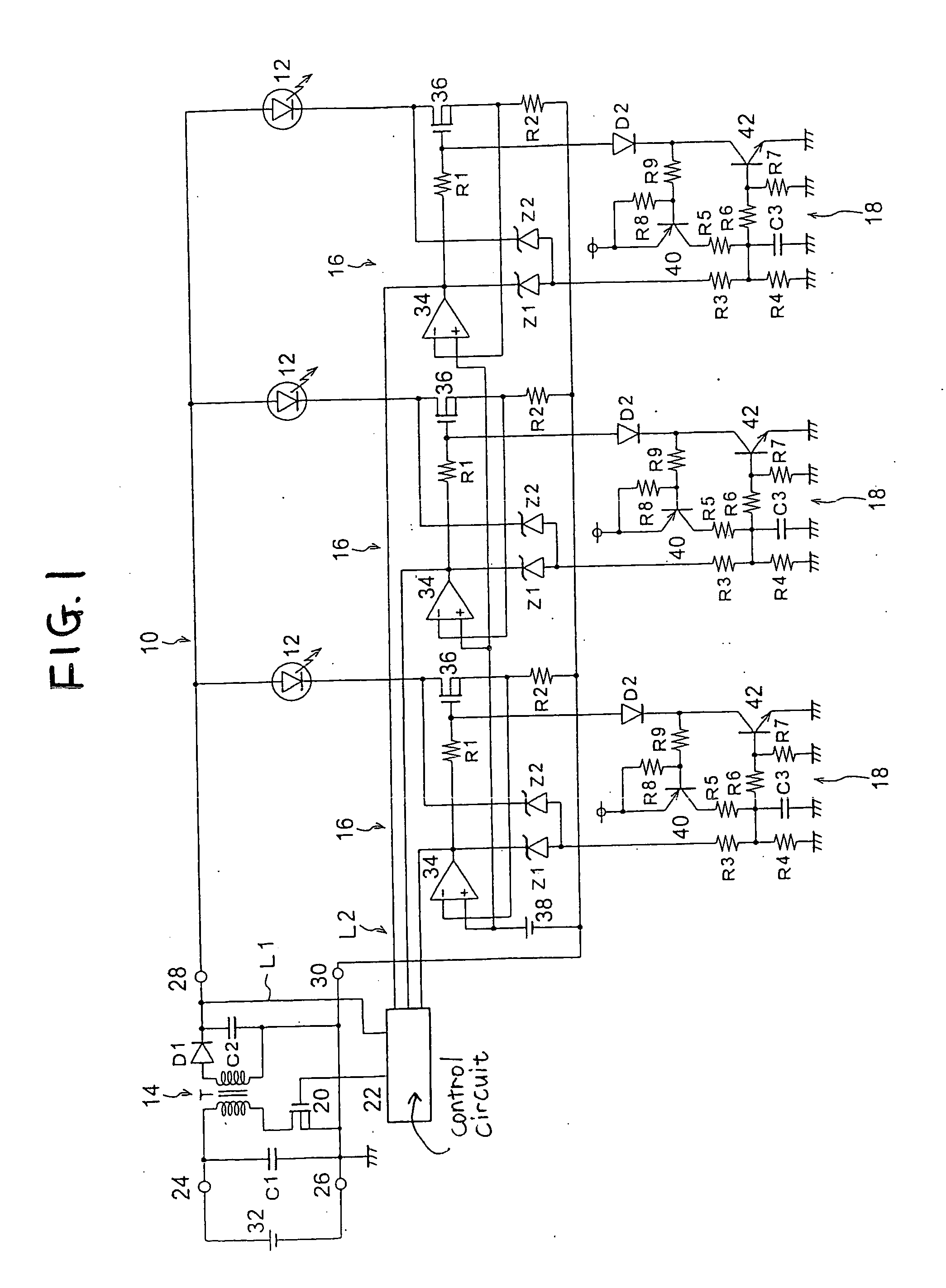
[0036] In FIG. 1 for the first embodiment, as one component of a vehicle lamp (light-emitting apparatus), a lighting control circuit 10 includes: one switching regulator 14, three series regulators 16 and three protection control circuits 18, relative to three LEDs 12. The individual LEDs 12 are connected in parallel as semiconductor light sources constituted by semiconductor light-emitting devices, and are connected in series to the series regulators 16 on the output side of the switching regulator 14. Either LEDs 12 connected in series or LEDs connected in parallel may be employed and connected in series to the individual series regulators 16. Further, the LEDs 12 can be constituted as light sources for various types of vehicle lamps, such as headlamps, stop lamps, tail lamps, front fog lamps and turn signal lamps.

[0037] The switching regulator 14 includes capacitors C1 and C2, a transformer T, a diode D1, an NMOS transistor 20 and a control circuit 22, while both terminals of the...

second embodiment

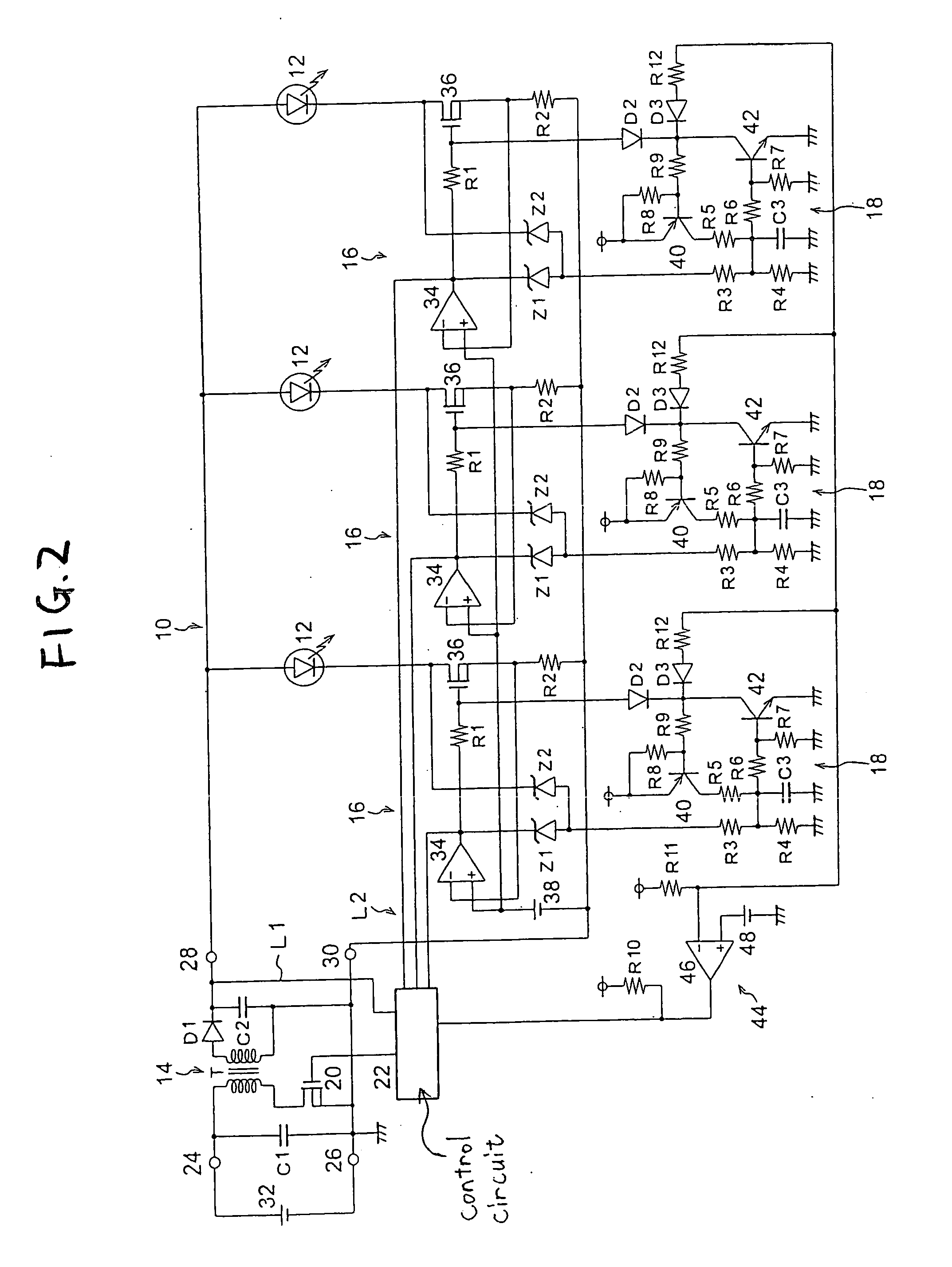
[0052] the present invention will now be described while referring to FIG. 2. According to this embodiment, an operation halt instruction circuit 44 is additionally provided as operation halt instruction means that issues an operation halt instruction to a switching regulator 14 when the number of protection control circuits 18 that have performed a protection control operation has reached a predetermined number. The remainder of the configuration is the same as that shown in FIG. 1.

[0053] The operation halt instruction circuit 44 includes resistors R10 and R11, a comparator 46, and three diodes D3 and three resistors R12 that correspond to those of the protection control circuits 18. The cathodes of the diodes D3 are connected to the collectors of NPN transistors 42, the junction of the resistors R10 and R11 is connected to the negative input terminal of the comparator 46, a reference power source for generating a reference voltage 48 is connected to the positive input terminal of ...

third embodiment

[0058] the invention will now be explained. According to this embodiment, an abnormality information output circuit 50 is additionally provided as abnormality information output means for monitoring protection control operations performed by protection control circuits 18, and when any of the protection control circuits 18 performs a protection control operation, it outputs abnormality information externally. The remainder of the configuration is the same as that shown in FIG. 2.

[0059] The abnormality information output circuit 50 includes a resistor R13 connected to a power source, and three diodes D4, corresponding to the protection control circuits 18. The cathodes of the diodes D4 are connected to the collectors of NPN transistors 42 and the junction of the resistor R13 and the diodes D4 is connected to an external connection terminal 52. The external connection terminal 52, for outputting the abnormality information externally, is connected to the power source via an LED 54, wh...


PUM


Abstract

The supply of a predetermined current to LEDs is controlled by using series regulators. In accordance with the controlled states of the series regulators, a switching regulator adjusts an output voltage relative to the LEDs to the maximum voltage. When a ground fault occurs at the anode of one of the LEDs, and when a short circuit occurs at the output terminal of the switching regulator and the output voltage drops abnormally, the operation of the switching regulator is halted. When the gate voltage of an NMOS transistor is raised due to the disconnection of one of the LEDs, or when the drain voltage of the transistor is raised due to a short circuit at one of the LEDs, a Zener diode becomes conductive and an NPN transistor and a PNP transistor are rendered on. Then, a current flows through a diode, and as the gate voltage has been lowered, the operation of the NMOS transistor is halted, so that the remaining, normal LEDs are protected when an abnormality occurs.

Description

[0001] The present application claims foreign priority based on Japanese Patent Application No. P.2004-292161, filed on Oct. 5, 2004, the contents of which are incorporated herein by reference. BACKGROUND OF THE INVENTION [0002] 1. Field of the Invention [0003] The present invention relates to a lighting control circuit for vehicle lamps, and particularly relates to a lighting control circuit for vehicle lamps that controls the lighting of a semiconductor light source constituted by a semiconductor light-emitting device. [0004] 2. Related Art [0005] There is a vehicle lamp wherein a semiconductor light-emitting device such as LEDs (Light Emitting Diodes) is employed as light sources. A lighting control circuit for controlling the lighting of LEDs is mounted on the vehicle lamp. [0006] In the lighting control circuit, one type of a lighting control circuit employs a switching regulator for controlling voltages to be output to LEDs based on the current supplied to the LEDs. Even when ...

Claims


Application Information

Patent Timeline
Patent Type & Authority Applications(United States)
IPC IPC(8): B60Q1/14H05B45/50
CPCH05B33/0815H05B33/0827H05B33/089Y02B20/341H05B45/50H05B45/46Y02B20/30H05B45/382H05B45/385
Inventor ITO, MASAYASUTAKEDA, HITOSHI
Owner KOITO MFG CO LTD
Why Eureka
Try Eureka