Brushless DC motor driving method and apparatus for it

a dc motor and motor technology, applied in the direction of motor/generator/converter stopper, dynamo-electric converter control, pump parameter, etc., can solve the problem of no way to use any hall element, and achieve the effect of low noise operation and high efficiency

Active Publication Date: 2006-04-20
PANASONIC CORP
View PDF4 Cites 30 Cited by
  • Summary
  • Abstract
  • Description
  • Claims
  • Application Information

AI Technical Summary

Benefits of technology

[0008] The objective of the present invention is to provide a brushless DC motor drive unit, capable of high-speed rotation with improved motor efficiency at low speed.
[0017] This makes it possible to realize low-noise operation with high efficiency during low-speed rotation, secure stable high-speed operation during high-speed rotation, and control peak current of effective current because the current waveform also comes closer to sine wave.

Problems solved by technology

Moreover, since the brushless DC motor is installed under environments of high temperature, high pressure, refrigerant ambiance, and oil ambiance in the compressor, there is no way to use any Hall element.

Method used


Image

  • Brushless DC motor driving method and apparatus for it
  • Brushless DC motor driving method and apparatus for it
  • Brushless DC motor driving method and apparatus for it

Examples


first embodiment

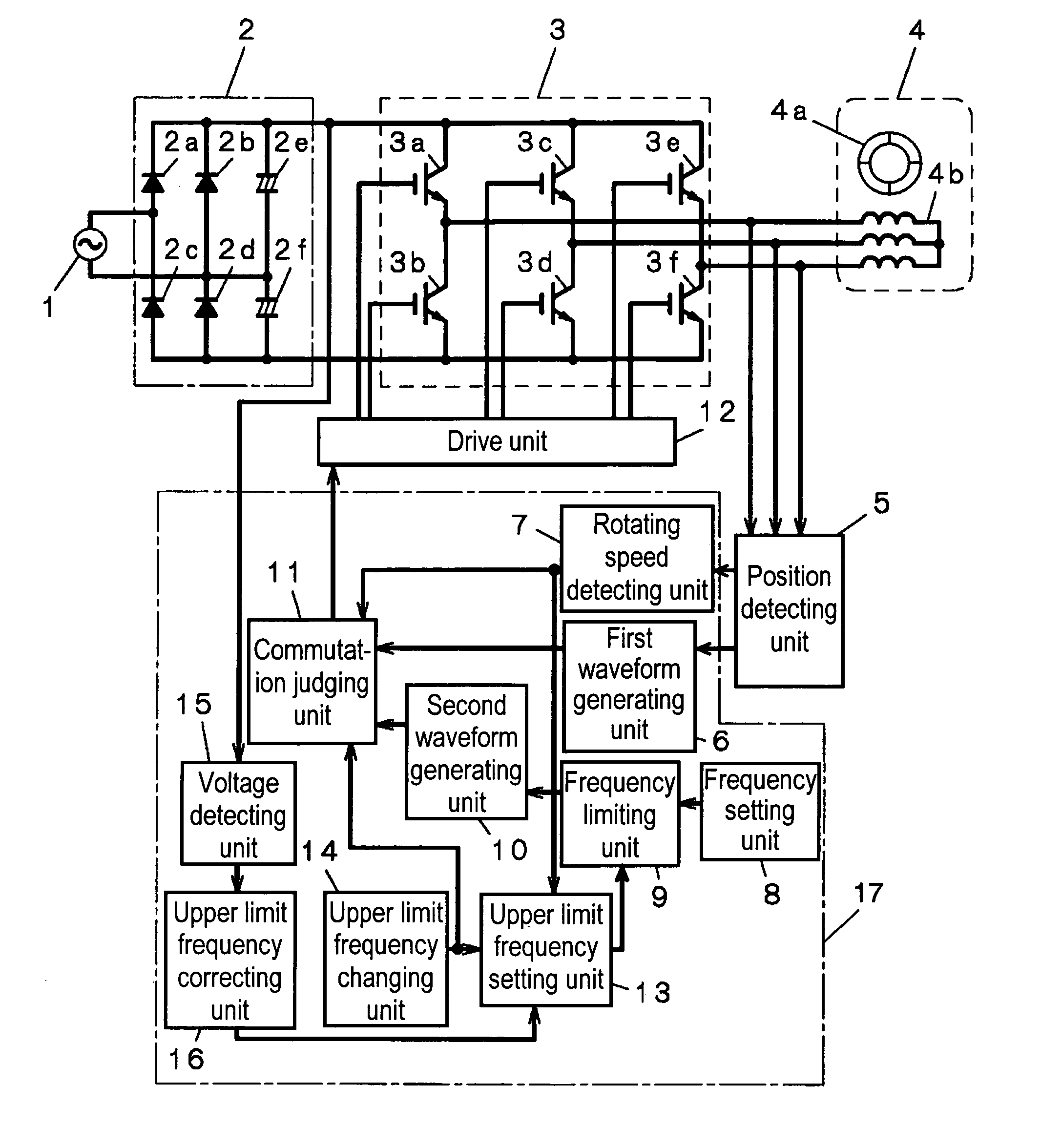
[0040]FIG. 21 is a block diagram of a brushless DC motor drive unit in the first embodiment of the present invention.

[0041] In the diagram, the commercial power source 1 is an AC power supply unit with a frequency of 50 Hz or 60 Hz and a voltage of 100V in Japan. The rectifier circuit 2 is composed of bridge-connected rectifying diodes 2a to 2d and smoothing electrolytic capacitors 2e, 2f. The circuit in the diagram, which is a voltage doubler rectifier circuit, provides a DC voltage of 280V from AC 100V input of the commercial power source 1. The rectifier circuit 2 may be other rectifier circuit such as chopper circuit with full-wave rectification or variable DC voltage, circuit switchable for voltage doubler rectification or full-wave rectification, etc.

[0042] The inverter circuit 3 is constructed with 6 switching elements 3a, 3b, 3c, 3d, 3e, 3f formed in three-phase bridge. The respective switching elements have parallel diodes in reverse direction for reflux current, but they...

second embodiment

[0072]FIG. 8 is a block diagram of the brushless DC motor drive unit of the second embodiment of the present invention. In FIG. 8, the portions which were already explained in the preceding embodiment are furnished with the same reference numerals, and any detailed explanation on them will be omitted.

[0073] The output voltage detecting unit 30 detects the output voltage of the rectifier circuit 2 through the W-phase terminal of the stator winding, when the switching element 3e of the inverter 3 is turned ON. The upper limit frequency correcting unit 16 sends out an output for correcting the upper limit frequency of the upper limit frequency setting unit 13, in response to the output from the output voltage detecting unit 30. The upper limit frequency is corrected upward if the voltage is higher than the standard, but is corrected downward if the voltage is lower than the standard. This makes it possible to maintain a stable high-speed rotation even in case of fluctuations of the su...

third embodiment

[0074]FIG. 9 is a block diagram of the brushless DC motor drive unit of the third embodiment of the present invention. In FIG. 9, the portions which were already explained in the preceding embodiments are furnished with the same reference numerals, and any detailed explanation on them will be omitted.

[0075] A shunt resistor 40 is provided between the rectifier circuit 2 and the inverter 3. The current detecting unit 41 detects the current flowing through the shunt resistor 40. The phase difference detecting unit 42 detects the phase difference between the current and the output voltage detected by the current detecting unit 41. This phase difference is 5°˜15°, in the case of low-speed operation when the brushless DC motor 4 is driven by the first waveform generating unit 6. However, this phase difference expands if the brushless DC motor 4 makes a high-speed operation with driving as a synchronous motor by the second waveform generating unit 10. At a phase difference over 60°, the ...


PUM


Abstract

A rectangular wave or a waveform similar to the rectangular wave is output with an conductive angle no less than 120° but no more than 150° during low-speed operation, but output a rectangular wave, a sine wave or a waveform similar to them with an conductive angle no less than 130° but under 180° by changing the frequency only while maintaining the PWM duty constant at high-speed operation, making it possible to realize high-efficiency and low-noise operation at low-speed operation, secure stable high speed, and prevent peak current of effective current because the current waveform also comes closer to sine wave.

Description

TECHNICAL FIELD [0001] This invention concerns a brushless DC motor driving method and an apparatus for it, more specifically a driving method of brushless DC motor most suited for driving the compressor of refrigerators and air conditioners, etc. and an apparatus for it. BACKGROUND ART [0002] The mainstream of refrigerators produced in recent years is constituted by large models with a capacity of 350 liters or over, and the majority of those refrigerators are represented by inverter-controlled refrigerators with highly efficient variable compressor speed. Many of compressors for those refrigerators adopt brushless DC motor having a rotor with permanent magnet, for the purpose of achieving higher efficiency. Moreover, since the brushless DC motor is installed under environments of high temperature, high pressure, refrigerant ambiance, and oil ambiance in the compressor, there is no way to use any Hall element. For that reason, a method of detecting the rotor position from the volta...

Claims


Application Information

Patent Timeline
Patent Type & Authority Applications(United States)
IPC IPC(8): H02P7/06F04B35/04
CPCF04B35/04F04B2201/1208H02P6/08H02P6/085H02P6/10
Inventor HAMAOKA, KOJITANAKA, HIDEHISAOUCHIYAMA, TOMONORI
Owner PANASONIC CORP
Why Eureka
Try Eureka